Do you have a question about the Speakman Sentinel Mark II and is the answer not in the manual?
Lists required tools and helpful supplies for installation.
Key considerations before starting installation, including temperature limits.
Essential safety advice to follow during installation.
Guidance on valve maintenance, customer support, and warranty.
Steps for cutting the wall opening and mounting the valve body.
Instructions for connecting shower and tub outlets via pipe or copper sweat.
Detailed steps for installing PEX tubing using the cold expansion method.
Procedure for flushing the valve and checking for water leaks.
Procedure to adjust the maximum hot water temperature setting.
Guidance for servicing the valve, including cartridge removal.
List of available repair parts for the valve.
Detailed diagram for CPV-PB-PXE model rough-in dimensions and connections.
Detailed diagram for CPV-PB-DV-PXE model rough-in dimensions and connections.
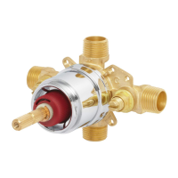
This document describes the installation, operation, and maintenance of the Speakman CPV-PB-PXE and CPV-PB-DV-PXE shower/bath valves.
The Speakman CPV-PB-PXE and CPV-PB-DV-PXE are pressure balance shower/bath valves designed to provide a consistent water temperature and flow. They are suitable for use with showerheads rated at 1.75 gpm (6.6 L/min) or higher. The "DV" in CPV-PB-DV-PXE indicates a diverter function, allowing the user to switch water flow between a showerhead and a tub spout. The "PXE" likely refers to PEX cold expansion connections. The valve includes a Temperature Limiting Stop (TLS) to prevent scalding by setting a maximum hot water temperature.
| Brand | Speakman |
|---|---|
| Model | Sentinel Mark II |
| Category | Control Unit |
| Language | English |