6
ASSEMBLY
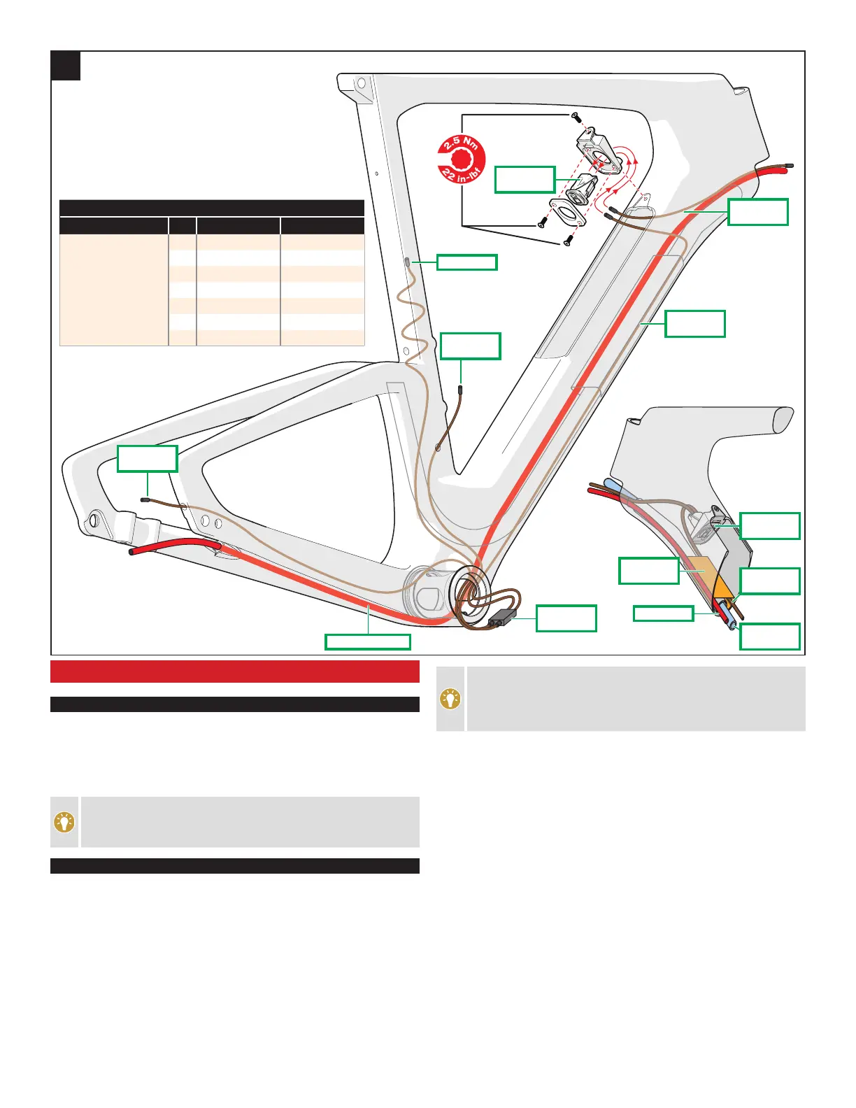
REAR BRAKE - FRAME
Fig.1: Route the rear brake hose through the frame, starting at the
chainstay port, under the bottom bracket shell, up the down tube and
under the non-drive side of the Nutrition Fuelcell shelf. Continue routing
the hose up the down tube until it exits the port below the head tube.
In order to reduce resistance during installation, we
recommend waiting until the rear brake hose is routed before
installing the junction A bracket in the down tube.
Di2 WIRE ROUTING - FRAME
Fig.1: The following are the recommended routing instructions for Shimano
Di2 wiring on the Shiv. Use the Park IR-1 Internal Cable Routing Kit to
simplify installation of shift wires or cable housings and brake housings.
All wires go over the bottom bracket shell, through the front of the
bottom bracket shell and out the side. The cranks must not be installed
until after the wiring routing is complete.
Make sure the junction A bracket (in front of the SWAT down tube box) is
removed from the down tube.
The frame has a permanently integrated guide tube for the
hydration system. Internal routing will run on either side of this
feature. It is normal to experience some resistance during the
routing process as a result.
Route the wires through the frame.
• Rear derailleur wire: Through the chainstay, starting at the rear
dropout port.
• Front derailleur wire: Down the seat tube, starting at the seat tube port.
• Battery wire: Down the seat tube, starting at the top of the seat tube.
• Lower down tube wire: Under the Nutrition Fuelcell shelf (on the
drive side) and down to the bottom bracket, while leaving the upper
plug dangling out of the Nutrition Fuelcell cavity.
• Upper down tube wire: Down through the port below the head tube
until it exits at the upper opening of the Nutrition Fuelcell cavity.
Guide four wires through the forward facing access hole in the bottom
bracket shell, and out of the frame.
Plug the wires into a Junction B box (SM-JC41), then place the junction
B box and wires back into the down tube, in front of the bottom bracket
shell.
Install the Junction A box (EW-RS910) into the Junction A bracket.
Torque the Junction A box cover bolts to 13 in-lbf / 1.5 Nm.
Di2 WIRE LOCATIONS/LENGTHS
LOCATION QTY TYPE LENGTH (mm)
REAR DERAILLEUR 1 EW-SD50-1 700
FRONT DERAILLEUR 1 EW-SD50-1 300
BATTERY 1 EW-SD50-1 700
DOWN TUBE (LOWER) 1 EW-SD50-1 600
DOWN TUBE (UPPER) 1 EW-SD50-1 300
BASEBAR
2 EW-SD50-1 500
EXTENSIONS
1 EW-JC130 (split wire) 50 / 550 / 550
FRONT
DERAILLEUR
BATTERY
BRAKE UNDER BB
JCT B BOX
(SM-JC41)
JCT A BOX
(EW-RS910)
LOWER
DOWN TUBE
UPPER
DOWN TUBE
REAR
DERAILLEUR
1
DRINKING
TUBE
LOWER DOWN
TUBE WIRE
REAR BRAKE
FUELCELL
SHELF
JCT A BOX
(EW-RS910)
 Loading...