4
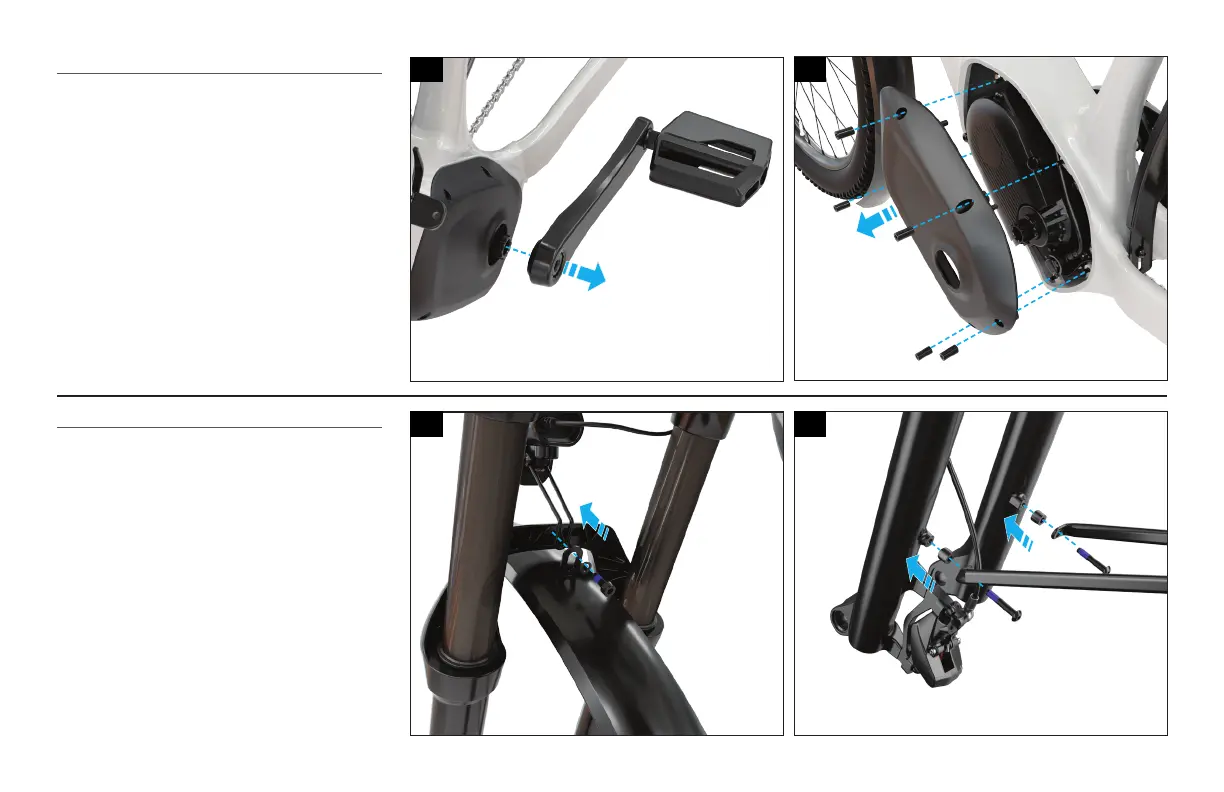
REMOVE THE CRANK AND MOTOR COVER
Fig. 4
Using an 8 mm hex key, remove the non-driveside
crank arm.
Fig. 5
Using a T20 Torx key, remove the non-driveside motor
cover.
ASSEMBLE THE FRONT FENDER.
Fig. 6
Mount the front fender directly to the fork arch with
the front light mounted between the fork arch and the
fender mounting bracket.
Using a 4 mm hex key, torque the bolt to 4 Nm / 35
in-lbf.
Fig. 7
Mount the front fender stays to the rear of the
suspension forks.
Using a 4 mm hex key, torque the bolts to 4 Nm / 35
in-lbf.
4
6
5
7