Chapter 2: Installing a ControlLogix 1756sc-CTR8-SC Module 2-7
Owner’s Guide 0300199-01 Rev. D
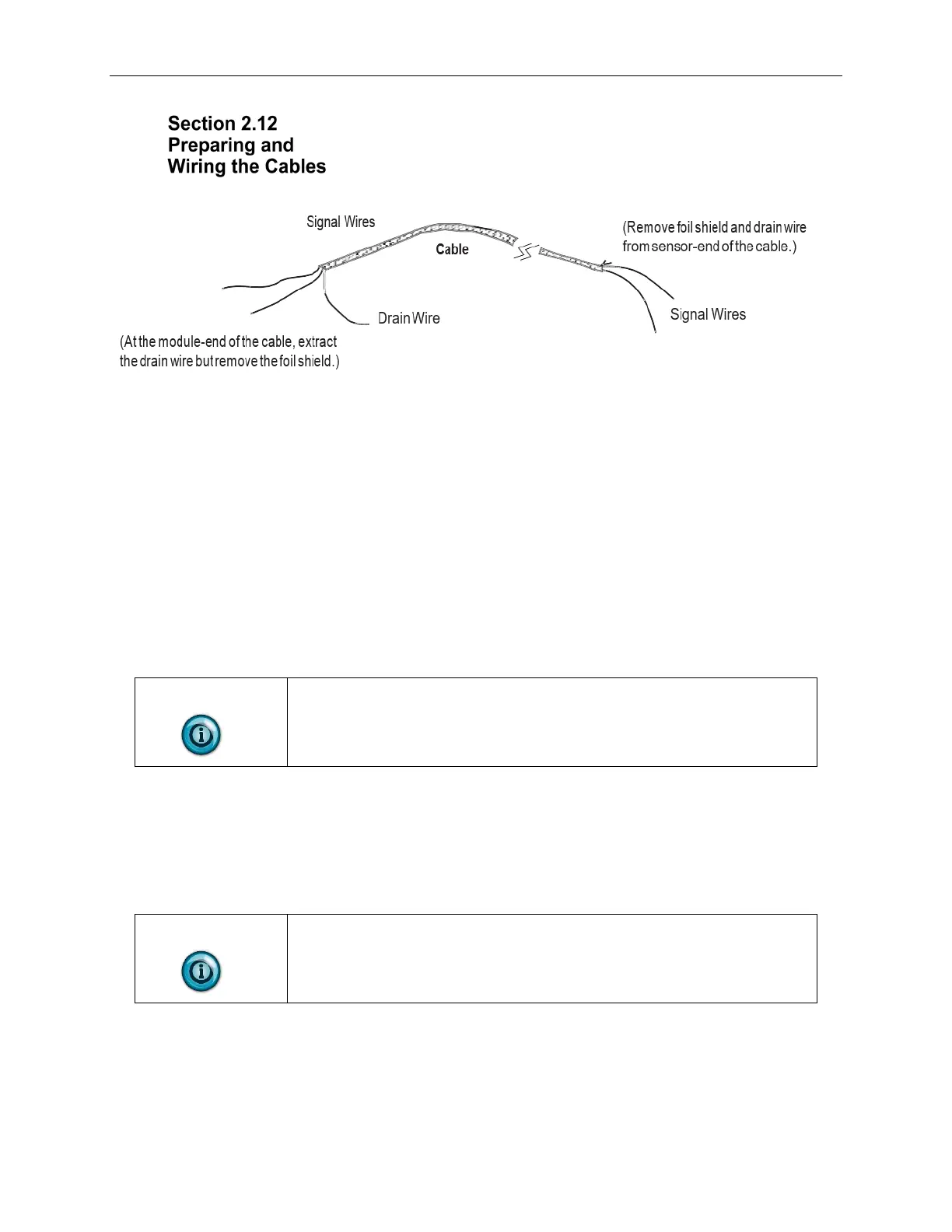
To prepare and connect cable leads and drain wires, follow these steps:
1. At each end of the cable, strip some casing to expose individual wires.
2. Trim signal wires to 5-inch lengths beyond the cable casing. Strip about
3/16 inch (4.76 mm) of insulation to expose the ends of the wires.
3. At the module-end of the cables (see figure above):
• Extract the drain wire and signal wires.
• Remove the foil shield.
• Bundle the input cables with a cable strap.
4. Connect pairs of drain wires together, Channels 0 and 1, Channels 2 and
3, Channels 4 and 5, Channels 6 and 7. Keep drain wires as short as
possible.
5. Connect the drain wires to the grounding lug on the PLC chassis.
6. Connect the signal wires of each channel to the terminal block.
NOTE
IMPORTANT: Only after verifying that your connections are correct for
each channel, trim the lengths to keep them short. Avoid cutting leads too
short.
7. At the source-end of cables from devices:
• Remove the drain wire and foil shield.
• Apply shrink wrap as an option.
• Connect to mV devices keeping the leads short.
NOTE
Important: If noise persists, try grounding the opposite end of the cable,
instead. (Ground one end only.)