IM-S02-30 CMGT Issue 14
18
FT43, FT44, FT46 and FT47 Ball Float Steam Traps
3.7
If the trap is to be situated in an exposed position, it should be either lagged or drained by a separate
small thermostatic trap such as the Spirax Sarco No.8, or Bydrain.
3.8
Always fit a non-return (check) valve downstream of any steam trap which discharges into condensate
return lines where back pressure is experienced. This is not commonly caused by a rising condensate
line. The check valve will prevent the steam space flooding when the inlet pressure is reduced or the
steam is shut off.
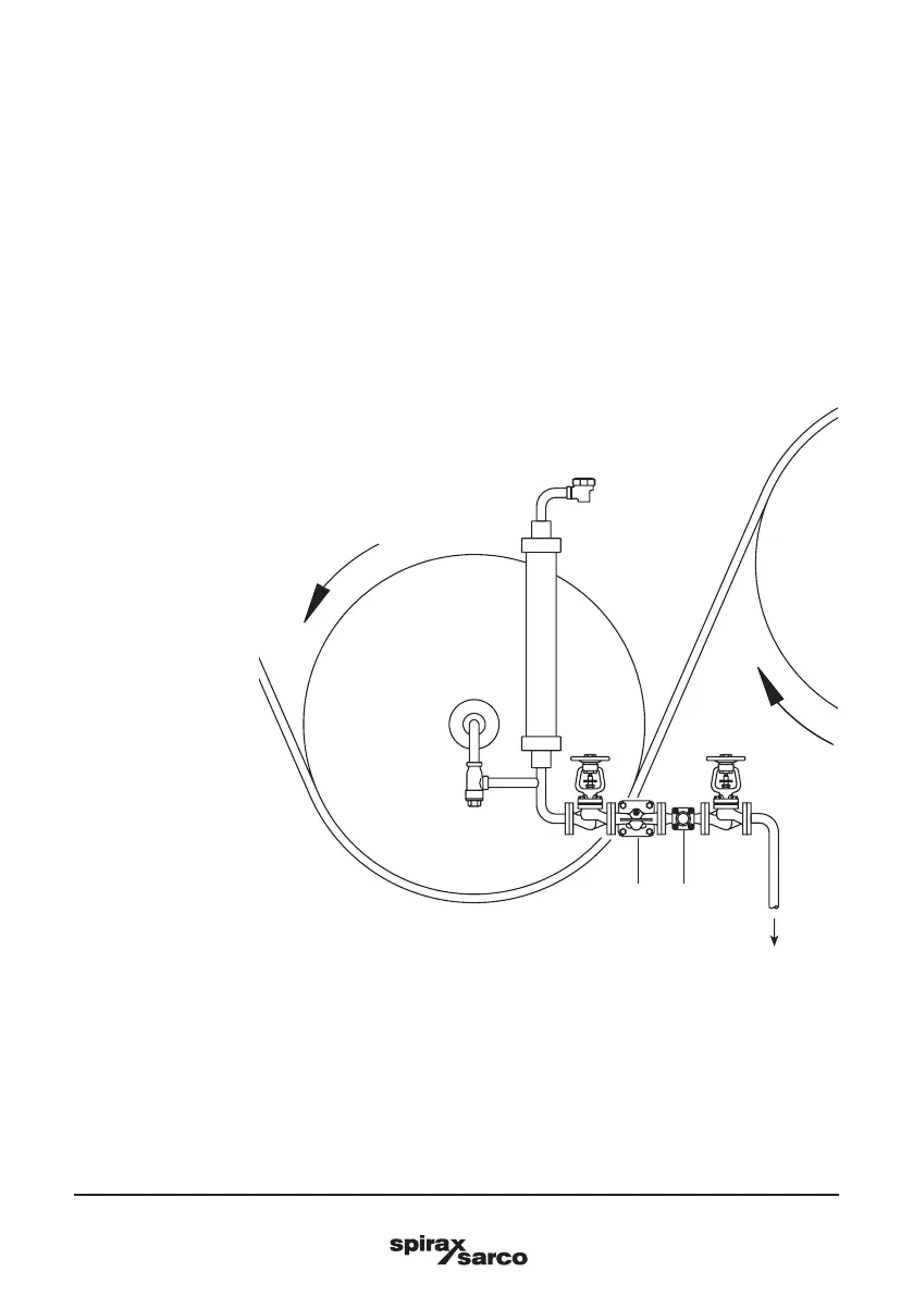
Fig. 7
Slow speed cylinder
drainage with system unit
Air vent
Float
trap
Sight glass
Condensate out
Strainer
Air bottle
Cylinder
3.6
Float traps should be fitted as close to the outlet of the plant to be drained as possible otherwise
the trap can steam lock. Steam locking occurs when the pipe between the condensate outlet and
the steam trap fills with steam and prevents condensate from reaching the trap. This can lead to the
system waterlogging which will affect plant efficiency. It is very similar to the air locking experienced
in water systems.
The most common application where steam locking is a risk is on rotating cylinders and other
applications where condensate is removed via a dip tube or siphon pipe. Steam locking can easily
be prevented by fitting the trap with a combined thermostatic air vent and an adjustable needle valve
(SLR), Figure 7 shows an FT-C trap fitted on a slow speed cylinder.
The adjustable needle valve (SLR) is opened by turning the spindle anticlockwise. The standard factory
setting is ½ turn which equates to an approximate steam 'bypass' of 22 kg/h @ 10 bar.
Site adjustment of the adjustable needle valve can be achieved by turning anticlockwise to increase
the bypass flow, and clockwise to reduce the flow.
When draining from a high speed cylinder application, there is need for large amounts of blow-through
steam to assist the flow of condensate out of the cylinder via the siphon tube.
In such cases the adjustable needle valve cannot handle such large amounts and an external bypass
with an adjustable needle valve is required. See Figure 8.