IM-P681-02 ST Issue 2
16
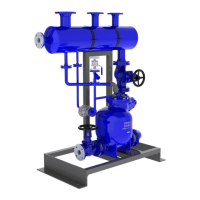
5. Triplex MFP14 - PPU
5.1 Installation
Safety notes:
Before actioning any installation observe the 'Safety information' in Section 1.
Important note: Please acknowledge the safe lifting points indicated on Figure 9.
5.2 Location
The MFP14-PPU should be located in a suitable position e.g. against a wall where the vent can
be easily piped to atmosphere. It is recommended that reasonable clearance is maintained
around the unit for ease of access.
1. Note: The receiver vent (Y) must be piped unreduced and unrestricted to a safe atmospheric
discharge point. The line should be vertical, if possible. If horizontal runs must be used, the
line should be pitched so that it is self draining to the receiver A suitably sized vent head should
be fitted to the top of the vent pipe to ensure safe discharge of flash steam. Refer
to Table 1 below for the recommended receiver vent pipe sizing.
Table 1. Recommended receiver vent pipe sizing
PPU size Reciever vent diameter
DN80 x DN50 3" x 2" 250 mm 10"
The recommended receiver vent size is based on:
- A maximum flash velocity in the receiver of 20 m / s.
- A maximum vent velocity of of 30 m / s.
- A maximum unrestricted vent pipe length of 10 m.
- A maximum condensate inlet pressure (discharge from steam traps) of 10 bar g.
2. Connect the condensate outlets (V) of the MFP14-PPU to the condensate return line -
See Figure 9.
3. Connect the condensate inlets (Z) to the process / equipment being drained.
4. Connect a 'U' bend water seal to the overflow point (X) and ensure that it is connected to a
safe discharge point. Ensure a suitable amount of water is filled into the 'U' bend before
commissioning the PPU. The 'U' bend water seal, during normal operation, is self-filling
and prevents 'flash steam' discharging from the overflow. It is recommended the 'U' bend
is at least 305 mm (12") deep. Always connect the overflow to a safe discharge point.
5. Connect the operating medium (steam) to the motive supply inlet (W).
6. The MFP14-PPU is now ready to be commissioned (see Section 5.3).
5.3 Commissioning
1. Slowly open the steam motive supply and exhaust isolating valves (item 7) to provide
pressure to the MFP14-PPU. Check that the motive trap (item 9 where fitted) is operational.
2. Open any isolation valves between the process being drained and the MFP14-PPU at
points (Z).
3. Open the inlet isolation valve (item 5) and the condensate outlet isolation valve (item 5)
in the condensate return line (point V).
4. Condensate should now start to flow into the main receiver (item 1) and into the pump (item 10)
when the plant is operational.
5. Check all flanged/screwed connections for any leakage.
6. Observe operation for any abnormalities. The pump (item 3) should cycle periodically
(minimum cycle time is 8 seconds) with an audible exhaust at the end of the pumping cycle.
This can be used to monitor the operation of the unit and meter the volume of condensate
pumped. If any irregularities are observed, recheck Sections 5.1 and 5.2 for proper
arrangement. Consult Spirax Sarco if necessary.
7. The system is now operational.
 Loading...