IM-P186-03 CH Issue 4
9
3.2 Start-up and adjustment for the SRV2S
Before final installation, all pipework should be thoroughly 'blown through' to remove dirt,
surplus
jointing material, etc.
Pressure
adjustment is made by turning the adjustment handwheel clockwise to increase
pressure
and anticlockwise to reduce pressure.
With
the upstream stop valve fully open and the downstream stop valve closed, slowly
increase
the downstream pressure by turning the adjustment handwheel clockwise until the
desired
pressure (shown on the downstream pressure gauge) is achieved.
Slowly open the downstream stop valve.
Under normal flow condition, the reduced pressure setting will fall slightly, but will control
under 'dead end' co ons. If required the pressure setting can be increased by readjusting the
SRV2S control. There will be a slight increase in set pressure under 'No-load' conditions.
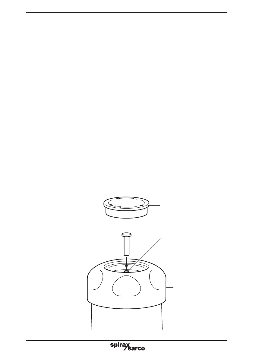
3.3 How to make the SRV2S tamper-proof:
- When the required set pressure has been achieved, lift out the coloured spring range ID
disc (grey, green or orange) from the adjustment handwheel recess. This is carried out by
inserting a small screwdriver blade under the edge of the ID disc.
- A small loose pin will be found in the recess in the adjustment handwheel.
- This tamper-proof pin is inserted into the locking hole 'A', and into one of a ring of 10 matching
holes in the top of the spring housing. The SRV2S is now tamper-proof.
- Replace the coloured spring range ID disc firmly into the recess of the adjustment
handwheel.
A
Fig. 3
Spring range ID disc
Tamper-proof pin
Adjustment handwheel