EasyManua.ls Logo

SPM BC100 - User Manual

SPM BC100
42 pages
Print Icon
To Next Page IconTo Next Page
Loading...
SPM Instrument AB • Box 504SE-645 25 Strängnäs • Sweden
Technical data are subject to change without notice.
Tel +46 152 225 00 • Fax +46 152 15075 • info@spminstrument.se • www.spminstrument.com
ISO 9001 certified. © Copyright SPM 2008-06. 71796 B
User Guide
Question and Answer IconNeed help?

Do you have a question about the SPM BC100 and is the answer not in the manual?

SPM BC100 Specifications

General IconGeneral
BrandSPM
ModelBC100
CategoryTest Equipment
LanguageEnglish

Summary

Instrument Overview

General Description

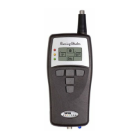
Provides an overview of the Bearing Checker's purpose and capabilities.

Start Up Procedure

Battery Management

Battery Check

Guide on how to check the battery status and voltage.

Instrument Settings

Shock Pulse Measurement Basics

The Shock Pulse Method

Explains the underlying principle of shock pulse analysis.

Carpet Value dBc Explanation

Defines and explains the significance of the carpet value.

Maximum Value dBm Explanation

Defines and explains the significance of the maximum value.

Rules for Measuring Points

Straight and Short Path Rule

Guidelines for selecting optimal measurement signal paths.

Single Interface Rule

Requirement for a single mechanical interface in the signal path.

Load Zone Measurement Rule

Specifies measuring points within the bearing's load zone.

Transducer Installation and Setup

Creating Acceptable Measuring Conditions

Removing Sources of Interference

Strategies to eliminate external signals affecting measurements.

Coping with Persistent Interference

Methods to manage interference when it cannot be removed.

Shock Pulse Transducers

Bearing Measurement Process

Inputting Bearing Data

Entering shaft diameter and RPM or dBi manually.

Entering Shaft Diameter and RPM

Calculating dBi from shaft diameter and RPM.

Entering dBi Manually

Direct input of the bearing's initial value (dBi).

Shock Pulse Measurement Execution

Transducer Line Test

Evaluating Bearing Condition

Reading Correctness Check

Verifying measurement accuracy and data input.

Shock Pulse Source Identification

Searching for the origin of detected shock pulses.

Bearing Fault Analysis

Determining the cause of bearing issues.

Identifying Shock Pulse Sources

Shock Pulse Patterns - Condition Codes

2 The Shock Pulse Pattern from a Damaged Bearing

Identifies the pattern indicating bearing damage.

Confirming Bearing Damage

Lubrication Test Procedure

Method to verify bearing condition using lubrication.

Temperature Measurement

Maintenance and Calibration

Related product manuals