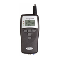
Instrument parts
1 Measuring probe
2 Temperature IR sensor
3 Condition indicators
4 Graphical display
5 Navigation keys
6 Measuring key and power on
7 Output for headphones
8 Transducer input
9 Measuring LED
10 Battery compartment
11 Serial number label
Instrument Overview
1
3
4
7 9
2
5
6
8
General description
The Bearing Checker is a shock pulse meter based on the well proven SPM method for quick and easy
identification of bearing faults. The instrument has a built-in microprocessor programmed to analyze
shock pulse patterns from all types of ball and roller bearings and display evaluated information on the
operating condition of the bearing.
Bearing Checker is battery powered and designed for use in harsh industrial environments. The graphic
display (4) gives the condition readings and the LED indicators (3) give an immediate evaluated bearing
condition in green-yellow-red.
The shock pulse transducer (1) of probe type is built-in. All types of SPM shock pulse transducers for adapt-
ers and permanent installation can also be used, connected to the transducer input (8). The dBi value is
programmed into the instrument and the measurement is started with key (6). The actual condition reading
is displayed on the graphical display (4) as a carpet value “dBc” and a maximum value “dBm”. The condi-
tion indicators (3) indicate the evaluated bearing condition in green-yellow-red. Headphones for listening
to the shock pulse pattern can be connected to the output (7).
The Bearing Checker can also be used for measuring surface temperature via the IR sensor (2), and for
detecting machine sound irregularities via headphones using the stethoscope function.
Internal or external probes can be used for listening.
11
10