Chapter 3: Programming
Chapter 3:2
Table 11 - Overload Trip Class
Setting
DIP Switch
#11
DIP Switch
#12
The controller incorporates, as standard, electronic overload
protection. This motor overload protection is accomplished
electronically with the use of internal current transformers on
each of the three phases. The controller’s overload protection is
programmable, providing the user with flexibility.
OFF OFF OFF
10 ON OFF
15 OFF ON
20 ON ON
Table 12 - Overload Reset
Setting
DIP Switch
#13
In manual reset mode, the fault can only be reset by pushing the
‘push to reset’ button on the front of the controller. In auto reset
mode, the unit will automatically reset when unit determines the
motor has cooled to 75% of its thermal capacity.
Manual OFF
Auto ON
Table 13 - Aux#1 Setting
Setting
DIP Switch
#14
The operation defines the operation of the Auxiliary contacts.
Normal mode means that the contact will change state
immediately when a start/run command is given. Up-to-Speed
mode means that the contact will change state only when the
controller is in bypass. Aux#2 when added will operate opposite
of this programming.
Normal OFF
Up-to-Speed ON
Table 14 - Motor Connection Type
Setting
DIP Switch
#15
In DELTA connection mode, the device is designed to control a 6
or 12 lead motor. In LINE connection mode, the device is designed
to control a 3 or 9 lead motor.
Delta OFF
Line ON
Table 15 - Stop Delay
Setting
DIP Switch
#16
When the delay is programmed, the motor will continue to run for
the programmed period of time after the run command is removed
from the controller.
0.0 Sec OFF
0.75 Sec ON
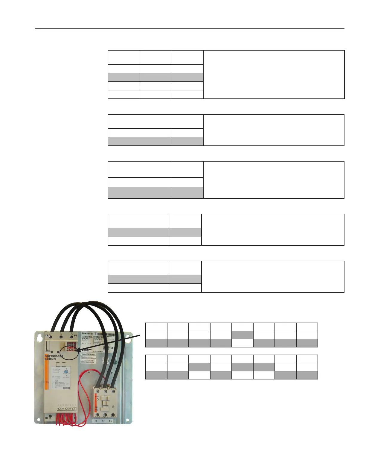
Factory DIP Switch Settings
1 2
3 4 5 6 7 8
ON ON
ON ON ON ON ON ON
OFF OFF OFF OFF OFF OFF OFF OFF
9 10
11 12 13 14 15 16
ON ON
ON ON ON ON ON ON
OFF OFF OFF OFF OFF OFF OFF OFF
 Loading...