Chapter 2:1
Chapter 2: Installation
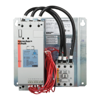
Prior to installation, unpack the starter panel from it’s packaging and perform a complete
visual inspection of panel. Inspect all components including the controller, wiring, and fault
contactor for damage related to shipping and handling. Claims for damage must be made to
the carrier as soon as possible after receipt of the shipment.
e small footprint of the starter makes it ideal for mounting in the same space previously
occupied by legacy solid state starters and traditional Full Voltage starters. e starter panel
does not require mounting requirements beyond the basic footprint of the panel.
e product incorporates a small cooling fan. ere are no additional cooling requirements
for the product; however it is good practice to leave at least 6 inches (15.24 cm) of free space
above and below the unit for ideal air ow.
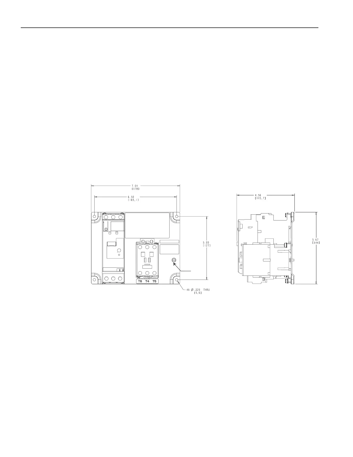
Figure 1 – Panel Dimensions for 32, 51, and 64 Amp Elevator Panels
CAT. XXXXXXXX SER. B
Dimensions in mm (in)
Weight 4lbs (2kg)
see
This screw is intended for securing: a) a prepared bonding conductor (such as one with crimped-
on lug); or b) a suitable terminal for connection of an unprepared bonding conductor (stripped wire
end). This screw is not intended for direct field wiring connection of an unprepared conductor or
equipment grounding conductor.
Unpacking
Mounting
Dimensions
Drawings
 Loading...