Chapter 3: Programming
Chapter 3:3
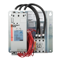
e front of the PCE controller contains a dial which is used for setting the actual FLA of
the motor. e label is designed to accommodate motors connected in the LINE or DELTA
mode. To determine the proper setting, look at the motors nameplate and set the dial
accordingly. e dial setting can be modied depending on the service factor of the motor as
follows:
e trip class should be set according to the motors maximum permissible locked rotor time
or the general thermal capabilities. Consult the motor manufacturer for recommendations on
setting the trip class.
Input and Output timing
= .9 X FLA
= 1 X FLA
= 1 X FLA
FLA _ _
Service Factor <1.15
Maximum Continuous
Rated (MCR) Motors
or
Service Factor _ _
Service Factor
>
1.15
11
7
32
19
22
13
Delta FLA
Line FLA
Motor FLA
Adjustments
Motor Overload
Trip Curves
)ces(t
1
10
2
864
1
10
2
864
Class 10
Class 15
1
10
2
864
Class 20
10
200
800
600
400
20
80
60
40
2
4
.2
.8
.6
.4
100
1000
8
6
1
10
200
800
600
400
20
80
60
40
2
4
.2
.8
.6
.4
100
1000
8
6
1
10
200
800
600
400
20
80
60
40
2
4
.2
.1
.1
.1
.6
.8
.4
100
1000
8
6
1
COLD START
HOT START
 Loading...