INSTALLATION, OPERATION and MAINTENANCE MANUAL | 29
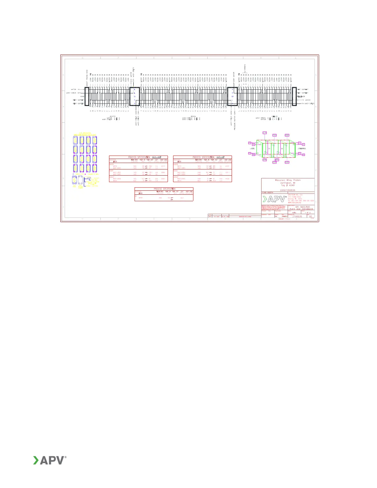
Figure 18: Typical plate arrangement diagram
Along the top of this diagram is a listing of each plate required, showing the hand of
each plate (Right or Left), the direction the gaskets face (Head or Follower) and the
plate punch code (blanking designation). The punch code indicates which ports are
open and allow flow. Additional codes may be listed indicating plates with drains (D) and
vents (V) or plates with end gaskets (K). Other symbols may be used to indicate special
support pads or gaskets. The customer drawing includes a key which illustrates the
punch codes. The punch codes are also illustrated in Figure 19 for vertical flow plates
and Figure 20 for diagonal flow plates. The punch codes may vary depending on the
manufacturing site.