28 | INSTALLATION, OPERATION and MAINTENANCE MANUAL
6.2. Plate Arrangement Diagram
Configuration of the Diagram
The plate heat exchanger is designed to perform a duty (or duties) by arranging the
plates in a specific sequence. This arrangement is represented schematically by the
plate diagram shown on the customer drawing. The schematic represents the fluid flows
by heavy lines with arrows and the plates by thin vertical lines. Plate ports that block
flow (not open) are represented by small black rectangles. An example of the plate
arrangement diagram is shown in Figure 18.
Each connection on the plate diagram is identified and labeled. The connections are
also identified on the dimensioned view or the isometric view of the plate heat
exchanger and the connection schedule.
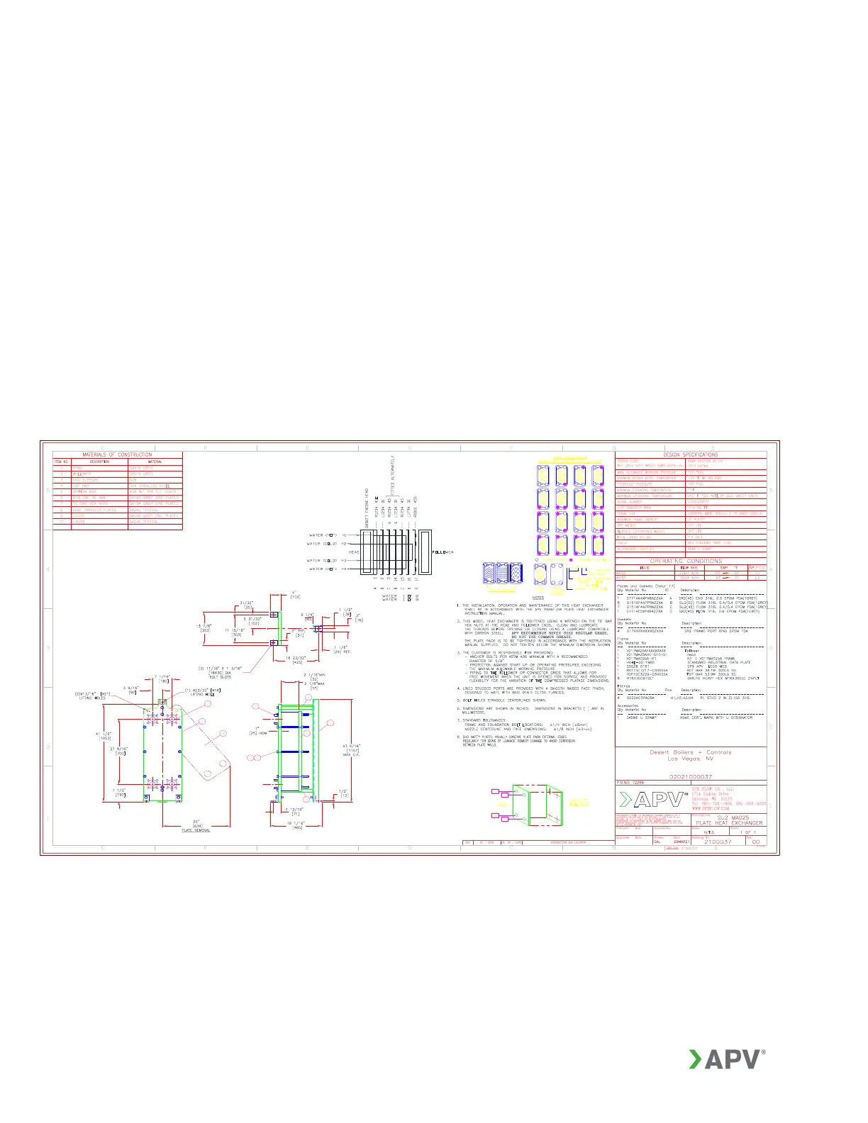
Figure 17: Typical GPHE customer drawing