32 | INSTALLATION, OPERATION and MAINTENANCE MANUAL
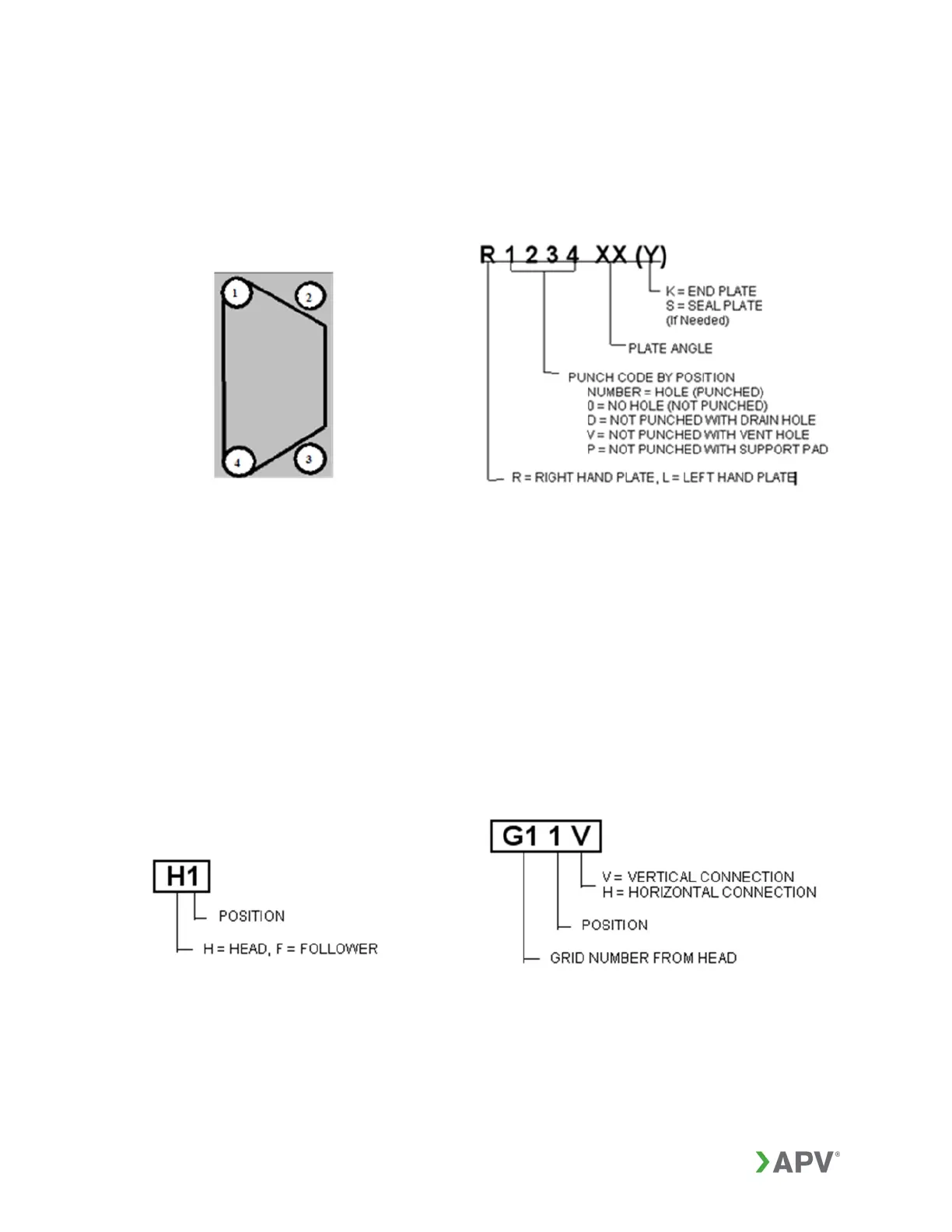
The plate punch code will use a five character code as shown in Figure 17 or 18. The
obsolete three and four character codes are shown for reference. The connection
positions (ports) are numbered as shown in Figure 21. The complete plate identification
number is constructed as shown in Figure 22:
Figure 21: Position numbering Figure 22: Plate identification number
The plate arrangement diagram and the customer drawing typically show the head or
fixed cover on the left. Frame connections are labeled with an H (head) or F (follower)
and a number corresponding to the connection position (Figure 23).
Connection grids are labeled with a four character code. The first character, “G”,
indicates this is a connection grid. The second character indicates the position of the
grid in the GPHE with 1 being the first grid from the head. The third character indicates
the connection position on the grid. The fourth character indicates the orientation of the
connection. Grid connections are labeled as shown in Figure 24.
Figure 23: Head / follower labeling Figure 24: Grid labeling