INSTALLATION, OPERATION and MAINTENANCE MANUAL | 33
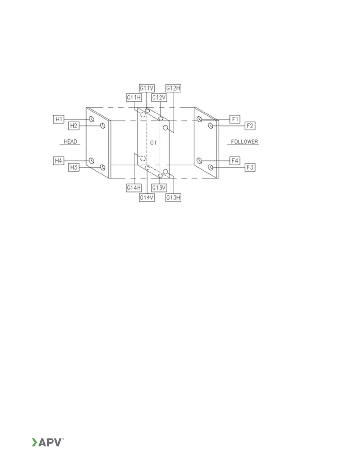
The head, follower, and connection grid labeling are shown in Figure 25.
Note: All possible connections are shown in Figure 25. Only the connection provided
will be shown on the customer drawing.
Figure 25: Head, follower, and connection grid labeling
Examples
A typical single pass arrangement using diagonal flow plates with all connections on the
head (Figure 26).
Note: PLATES MUST BE ARRANGED ALTERNATELY LEFT AND RIGHT. FOR
CONVENIENCE ON THE DRAWING, WHERE BLOCKS OF R1234 AND L1234
PLATES OCCUR, THE TOTAL NUMBER OF EACH IS GIVEN, BUT ONLY ONE OF
EACH IS SHOWN.
Figure 27 shows a two-section arrangement with connections on the head, follower,
and connector grid. It also shows the use of the special codes to indicate drain plates
(D), support pads (P) and seal plates (S) typical for certain plates.