36
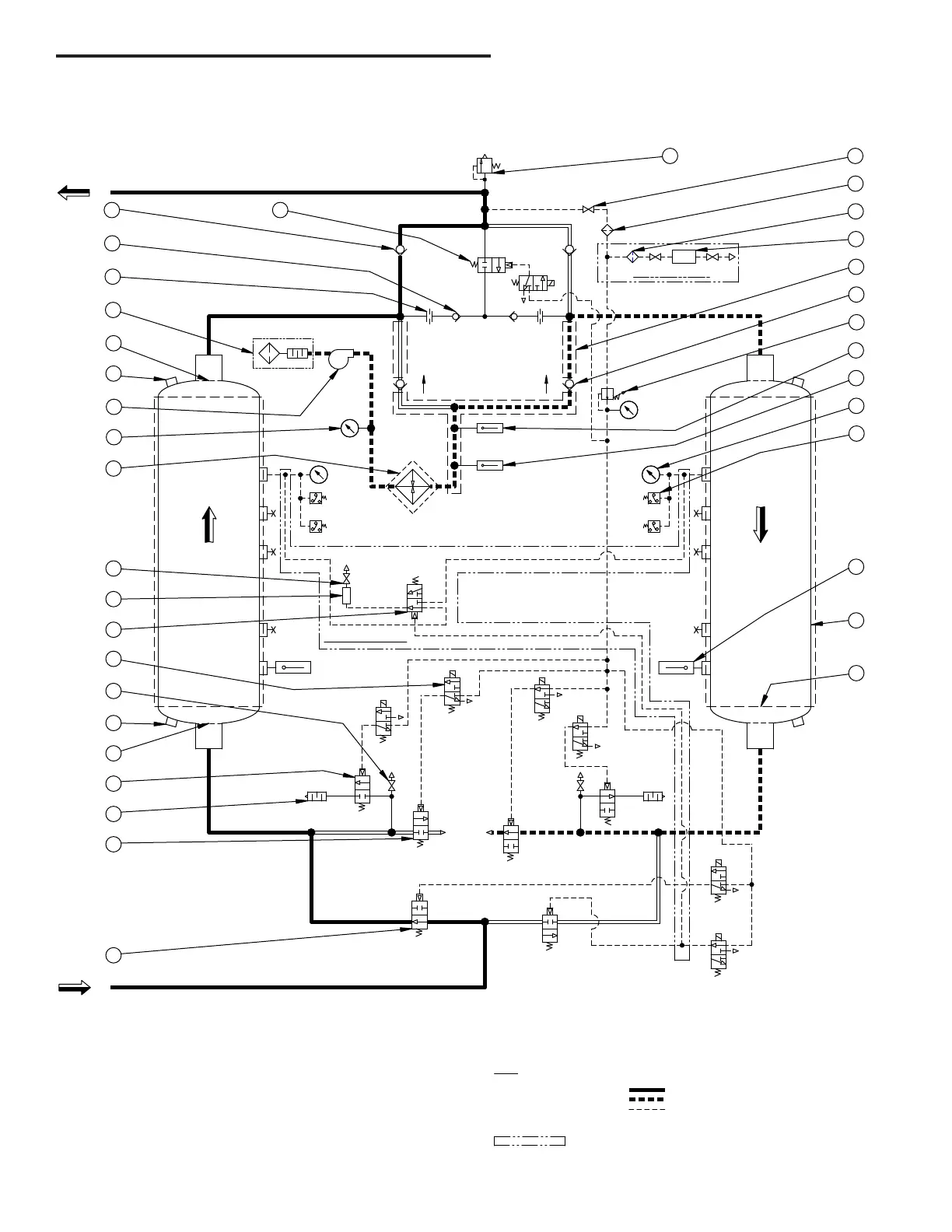
P&ID Schematic - Models 500 through 600
(Contact factory to request certied drawings)
RIGHT
WET GAS
INLET
DRY GAS
OUTLET
RTD 3
3
1
2
ENERGY MGMT OPTION
EXH.
1TC
SET @ 370°F
LEFT
20
CHAMBERCHAMBER
REGENDRYING
SOL 'C'
SOL 'D'
RTD 2
100 PSIG
SET AT
V7 V8
V6V5
V4
V3
6
19
25
19
21
3
22
14
13
44
SET @ 165 PSIG
8
7
13
43
9
54
42
5
17
2
11
12
SOLENOID VALVES 'B', 'D', & 'G' ARE SHOWN ENERGIZED,
SYMBOLS ARE PER ANSI Y32.10 "GRAPHIC SYMBOLS FOR FLUID POWER DIAGRAMS."
SOLENOID VALVES 'A', 'C', 'E', & 'F' ARE SHOWN DE-ENERGIZED.
AS SHOWN FLOW DIRECTION IS:
INDICATES OPTION
3.
2.
1.
PILOT GAS LINE
RIGHT CHAMBER REGEN
LEFT CHAMBER DRYING
15
29
18
NOTES
4.
DPA
DEWPOINTER OPTION
10
1
SOL 'B'
SOL 'A'
(RTD4/HS1)
M
23
24
28
SOL 'E'
V11
27
4 26
V12 V13
V9
EXH.
SOL 'F'
EXH.
RTD 1
V1 V2
SET @ 650°F
SOL 'G'
V10
16
SET @ 176°F
SET @ 176°F
2PS
SET @
45 PSIG
SET @
5 PSIG
4PS
1PS
3PS
45 PSIG
SET @
SET @
5 PSIG
44A
 Loading...