Waukesha Cherry-Burrell
®
Brand W60/W80 Valves Maintenance
02/2020 95-03022 Page 39
Servicing Actuators:
U-cups, O-rings and
Bearings
Shut off the air and disconnect the air supply line to the actuator.
Disconnect/lockout the electrical power to the valve.
Valves with Control Module
For control top information, please refer to publication 95-03083.
For additional product information, please see our website at
spxflow.com/en/waukesha-cherry-burrell/resources/product-
literature/.
O-ring and Bearing Replacement: 4”, 5”, and 6"
Actuator
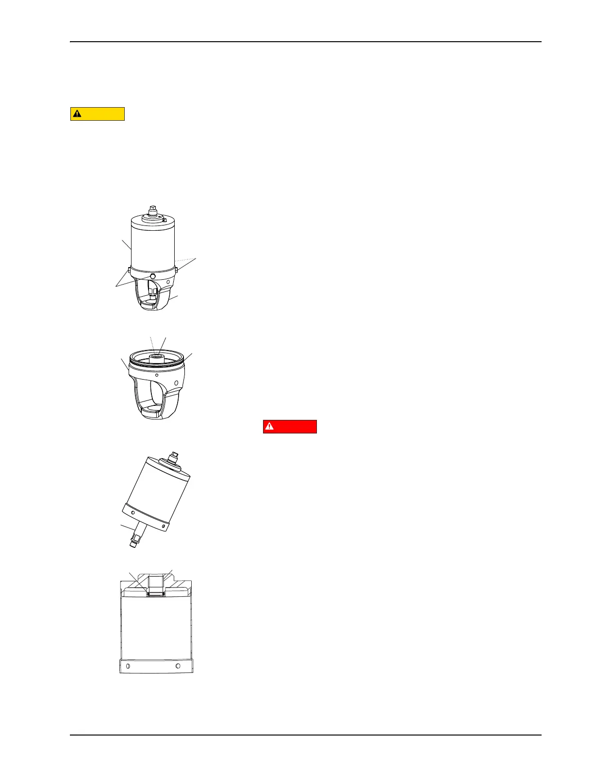
1. Remove the cap screws (Figure 32, item 9) and pull the yoke
(item 12) from the actuator cylinder (item 4).
2. Remove the yoke (Figure 33, item 4). Inspect the lower stem
O-ring (item 6) and cylinder O-ring seals (item 7).
3. Remove the worn O-ring seals. Coat the new O-ring seals
with Dow Corning
®
#7 Silicone Lubricant or equivalent, and
replace them.
4. Remove the PTFE guide bearing (Figure 33, item 5) by
placing a screwdriver behind the bearing to pry it away from
the wall of the yoke. Use needle-nose pliers to grip and
remove the bearing.
5. Pull the lower stem (Figure 34, item 3) to remove the caged
spring assembly from the actuator cylinder.
Do not use air to remove the caged spring assembly.
6. Remove and inspect the upper stem O-ring (Figure 35, item
6) in the top of the actuator cylinder.
7. Remove the worn O-ring seals. Coat the new O-ring seals
with Dow Corning
®
#7 Silicone Lubricant or equivalent, and
replace them.
8. Inspect and replace the PTFE guide bearing (Figure 35, item
5) in the actuator cylinder as needed.
Although WCB fully-maintainable
actuators are designed with a contained
spring for safety, always use caution
when handling any piston/spring
assembly as any compressed coil spring
can be extremely dangerous.
Figure 32: Remove Yoke
Figure 33: Remove Yoke O-ring and Guide
Bearing
Figure 34: Pull Lower Stem
Figure 35: Remove O-ring and Bearing

 Loading...