© 2013–2017 Schneider Electric All Rights Reserved
80043-808-02 Rev. 02 I-Line™ Combo Switchboards
03/2017 Installation—QO and QOB Circuit Breaker Installation and Removal
19
ENGLISH
QO and QOB Circuit Breaker Removal
Refer to Figure 6, QO and QOB Circuit Breaker Installation and Removal,
on page 19, for the following instructions.
1. Turn OFF all power to the I-Line Combo switchboard.
2. Turn the circuit breaker OFF.
3. Remove the large interior trim cover and the lighting section interior
trim cover (Figure 2, Interior Trim Removal, on page 12).
4. Remove the load wire. Secure the wire and cover the
exposed end.
5. Disengage the branch connector.
For QO Circuit Breakers:
— Pull outward until the plug-on jaws fully disengage the
branch connector.
For QOB Circuit Breakers:
— Loosen the screw(s) in the circuit breaker connector and pull the
circuit breaker off of the branch connector.
6. Snap the wire terminal end of the circuit breaker off of the
mounting rail.
7. Insert circuit breaker blank fillers in the lighting section interior trim
cover (Figure 8, Lighting Section Interior Trim Preparation,
on page 21).
8. Reinstall the lighting section interior trim cover and large interior
trim cover.
9. Ensure the I-Line section connection is free of debris
before re-energizing.
10. Re-energize the I-Line Combo switchboard.
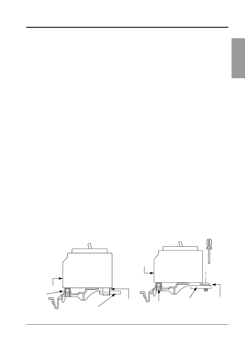
Figure 6: QO and QOB Circuit Breaker Installation and Removal
C
L
QOB
Branch
connector,
mounting hole
(not shown)
Mounting
rail
Wire
terminal
Plug-on jaw
(circuit breaker
connector)
Mounting
rail
Wire
terminal
Bolt on
connector
screw(s)
Branch
Connector
80043-808-01.book Page 19 Wednesday, March 22, 2017 12:31 PM
 Loading...