A20830
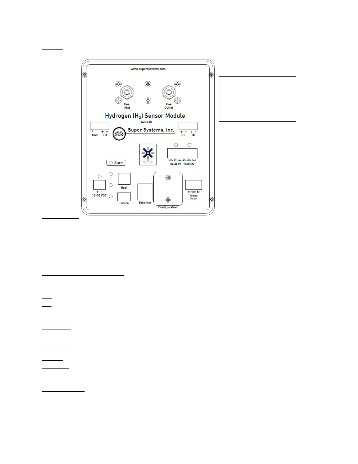
Figure 2 - Connections diagram for A20830
**Note that both the A20829 and A20830 will accept 10 – 30 VDC power. They are commonly
powered using a 24 VDC supply. When a Lambda O
2
sensor is required, consider using a 12 VDC
supply for both the SGSM and the Lambda sensor. SSi offers a 12 VDC supply for this option.
Connection Ports & Function
HMI: This is the connection for an HMI.
TH: This connection port is N/A for this product.
O2: This is the port for the Lambda O
2
analog sensor.
TC: This connection port is N/A for this product.
RS485 #1: This is a communications port used for when this device is the Client.
RS485 #2: This is a communications port used for when this device is the Host to another
device.
10-30 VDC: This is the port to supply power to the SGSM.
Host: This is the USB Host port.
Device: This is the USB Client port.
Ethernet: This is the Ethernet port.
Configuration: This is where dip switch settings can be changed for the Modbus
communications address.
Analog Output: These ports are for analog output #1 and #2.
 Loading...