Figure 5 – Modbus DIP switch location for A20829
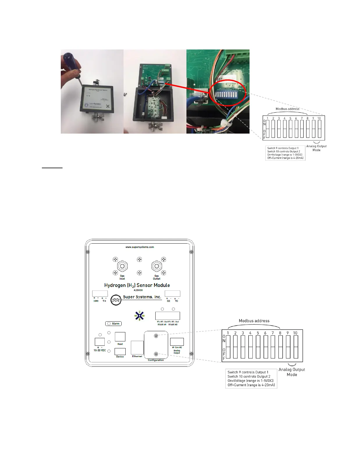
A20830
The DIP switches are accessible from the front of the unit without having to remove the cover
plate.
1. Verify that the unit is not powered. Unplug the power connector to remove power.
2. Remove the two (2) 6-32 screws from the access plate labeled, “Configuration.” This
will expose the DIP switches.
3. Move the DIP switches accordingly for the Modbus address listed in Appendix A.
4. Secure the cover plate with the two screws.
Figure 6–Modbus DIP switch location for A20830