Flash memory interface PM0059
6/29 DocID15687 Rev 5
2 Flash memory interface
2.1 Introduction
The Flash memory interface manages CPU AHB I-Code and D-Code accesses to the
1 Mbyte (64 Kbit × 128 bits) Flash memory. It implements the erase and program Flash
memory operations and the read and write protection mechanisms.
The Flash memory interface accelerates code execution with a system of instruction
prefetch and cache lines.
2.2 Main features
• Flash memory read operations
• Flash memory program/erase operations
• Read / write protections
• Prefetch on I-Code
• 64 cache lines of 128 bits on I-Code
• 8 cache lines of 128 bits on D-Code
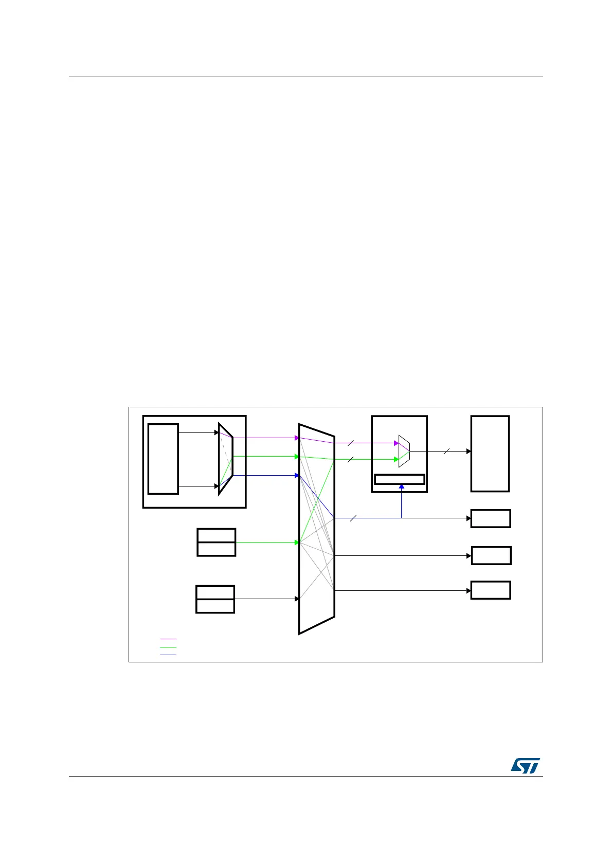
Figure 1 shows the Flash memory interface connection inside the system architecture.
Figure 1. Flash memory interface connection inside system architecture
#ORTEX
CORE
%THERNET
53"(3
$-!
$-!
$CODEBUS
)#ODEBUS
#ORTEX-
)#ODE
$#ODE
3BUS
PERIPH
&LASH
MEMORY
&LASHINTERFACE
32!-S
!("
PERIPH
&,)4®ISTERS
&3-#
&LASHMEMORY
BUS
BITS
BIT
!("
INSTRUCTION
BUS
!("
DATABUS
BIT
!("
SYSTEM
BUS
BIT
!CCESSTOINSTRUCTIONSIN&LASHMEMORY
!CCESSTODATALITERALPOOLIN&LASHMEMORY
&,)4®ISTERACCESS
AI