19
21
17
22
ASSEMBLY INSTRUCTIONS (cont.)
12. Attach the jack pump handle (#20) to the handle bracket
on the mainframe. Secure using 3/8“ x 2-1/2“ bolt w/ lock-
nut.
13. Insert 3/8” x 2-1/2” bolt through the hole just behind
the pump handle bracket. Using two nuts leave 1-3/4” of the
bolt sticking out from the mainframe. This acts as a rest for
the pump handle.
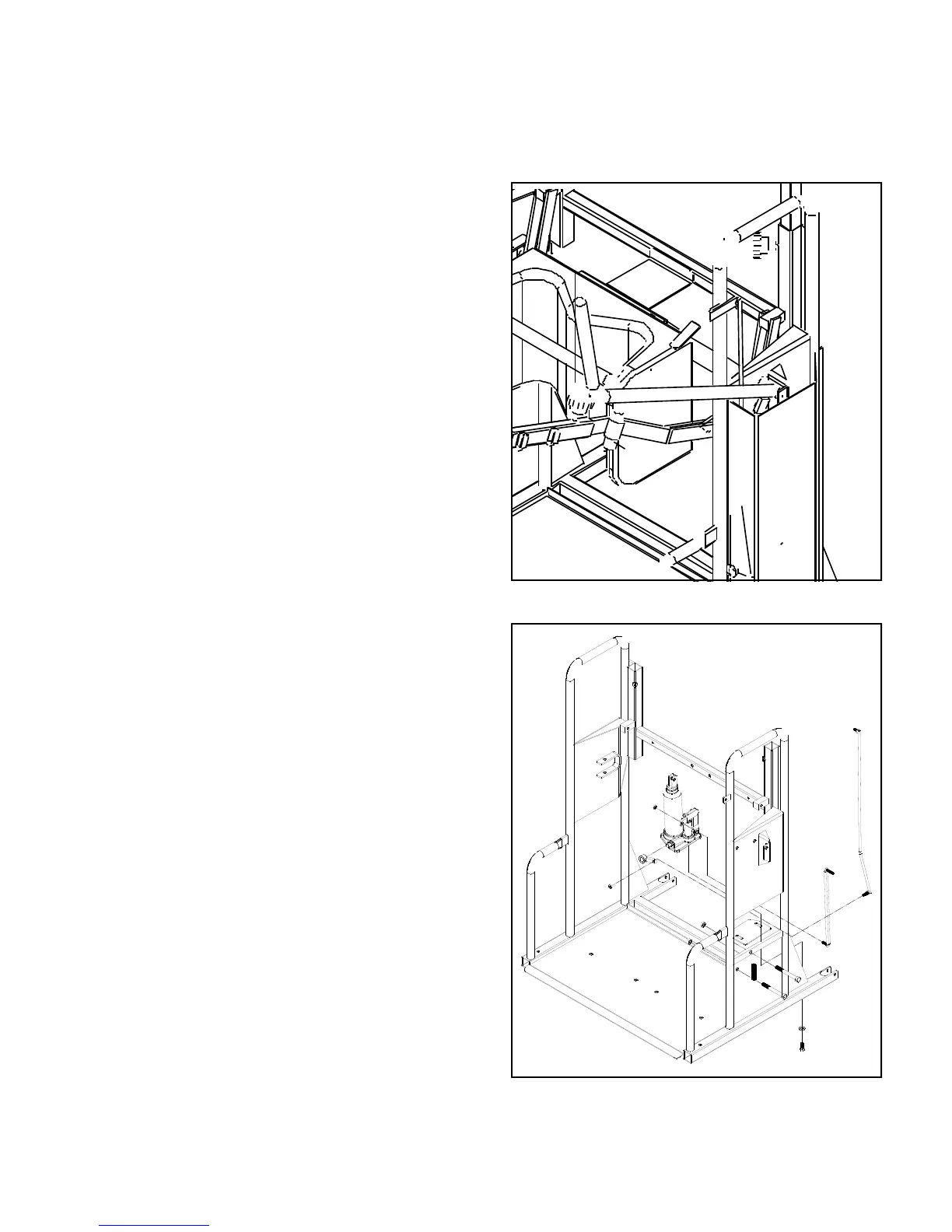
14. Attach the jack release lever (#21) to the tab located
toward the top of the mainframes right upright using 1/4“ x
3/4“ bolt w/ flatwashers and locknut. See image #3 at right
15. Attach the pump handle linkage (#19) to the jack pump
linkage, and to the mounting ear on bottom of the pump han-
dle. Secure using 1/4“ locknut. See image #4 at right for
proper mounting direction.
16. Attach the jack lobe (#17) to the jack release valve.
Tighten the allen screws on the jack lobe. See image #4.
17. Attach the jack release linkage (#22) to the jack
lobe,and the release lever. See image #4.
At the hole just below and to the rear of jack repeat step 13
with spring (#32) on the bolt. Secure spring, and release lever
linkage with nut, secure to release lever with nut also. (refer
to main diagram on pg. 8 for proper direction)
18. Insert vertical adjust tube (#24) into the mainframe re-
ceiver tubes. Secure at desired height with threaded knobs.
(height can be adjusted at any time)
19. IMPORTANT: TABLE TOP ASSEMBLY
1. Insert table frame (#27) into right and left insert
slides (#25 & #26). Secure with two adjustment knobs.
2. Slide the table frame (#27) and the insert slides (#25 &
#26) into the table adjust vertical tubes (#24). Secure
using 10-24 x 1-1/4” machine screws with locknuts.
3. Secure chest pad bracket (#29) to the table frame
(#27) tubes using pop rivets.
4. Slide table glass (#28) into table frame and under table
frame tabs. Secure table glass (#28) to chest pad
bracket (#29) using two 10-24 x 3/4” machine screws
with locknuts.
4. Mount the chest pad (#30) to the chest pad bracket
(#29) using 10-24 x 1/2” machine screws.
5. Attach the table clips (#31) to the chest pad using 10-24
x 1/2” machine screws. On the other end secure to the
table frame tubes using pop rivets.
20. Attach side cover (#23) to the outside of mainframe
over jack assembly using self-tapping screws.
Page 10
IMAGE #4
IMAGE #3
NOTE: Refer To Main Diagram on Pg. #8 for vis-
ual unless otherwise specified.
20
 Loading...