ASSEMBLY INSTRUCTIONS
16
18
IMAGE #2
IMAGE #1
2
3
4
5
6
9
7
38
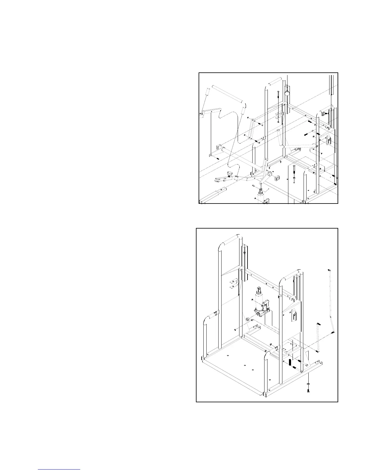
NOTE: Refer To Main Diagram on Pg. #8 for vis-
ual unless otherwise specified.
1. Insert the two mainframe support legs (#14) into bottom
rear mainframe (#1) tubes. Secure using 5/16” x 1-1/2” Roll
Pin.
2. Attach the two wheels (#15) to the front of the mainframe
bottom tubes using 1/4” x 1-1/2” bolt w/ locknut
3. Insert the drive bar (#2) with the nylon bushings (#3) on
each end into mainframe. Secure in the u-mounts located in-
side the mainframe using 5/16“ x 2-1/2“ bolt w/ locknut. See
image #1 at right.
4. Attach the linkage plates (#4) to the block mounts on the
mainframe using 1/4” x 1-3/4” bolt w/ locknut.
5. Attach the right and left lift arms (#5 & #6) to the drive bar
arms. (drive bar arms go between the lift arm plates) Secure
using 5/16“ x 3/4“ roll pin. The bottom of the lift arms attach
at the bottom of the drive bar and in between the linkage
plates on each side with 1/4“ x 1-3/4“ bolt w/ locknut. Slide
the adjustable lift arm hooks (#7 & #8) onto the lift arms and
secure using the threaded knobs (#10). NOTE: Desired posi-
tion can be determined at any time.
6. Insert the stabiliser tube (#9) into the lift arm tubes on each
side. Secure with self-tapping screws through stabilizer tube
and lift arm tube.
7. Attach the jack mount bracket (#18) to the mainframe.
Bracket mounts at the lower right or left (depending on model
ordered) side of mainframe, inside of frame upright. See im-
age #2 at right. Secure using 3/8“ x
1-1/2“ bolt w/ locknut.
8. Mount the hydraulic jack (#16) to the jack mount bracket
using two 5/16“ x 1/2“ bolt w/ flatwasher. NOTE: Jack
mounts on with the pump linkage to the outside. See image
#2 at right.
9. Attach the jack clevis to the drive bar right outside arm us-
ing pin (#38) and cotter pin. see image #1 at right.
10. IMPORTANT: Assemble the knee pad mount (#11),
the two slide plates (#12), and the knee pad (#13) simultane-
ously. Place knee pad mount (#11) between the slide plates
(#12). Center this assembly and attach to the knee pad (#13)
using 10-24 x 3/4” machine screws, two flatwashers under the
slides (#12) to provide clearance for the knee pad mount
(#11) slides.
11. Attach the whole knee pad assembly to the mainframe
front cross tube. Secure using two 10-24 x 1/2“ machine
screws. NOTE: The channel on the knee pad mount fits over
the drive bar.
1
Page 9
 Loading...