G
greenlucasAug 12, 2025
What to do if my Standard Horizon Transceiver fails to power up?
- CcantudianeAug 13, 2025
First, check the 12VDC battery connections and the fuse. Also, ensure that you press and hold the PWR/VOL knob to turn the radio on.
What to do if my Standard Horizon Transceiver fails to power up?
First, check the 12VDC battery connections and the fuse. Also, ensure that you press and hold the PWR/VOL knob to turn the radio on.
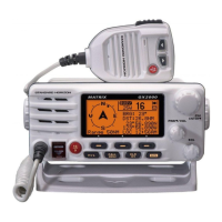
Why does my Standard Horizon MATRIX AIS/GPS GX2200E Transceiver blow a fuse when connected to the power supply?
A blown fuse typically indicates reversed power wires. Ensure the red wire is connected to the positive (+) battery post and the black wire to the negative (–) post. Check the power cable for DC voltage and replace the fuse (6A). If the fuse continues to blow, it's recommended to contact your Dealer.
Why does my Standard Horizon MATRIX AIS/GPS GX2200E show 'HI BATTERY' or 'LO BATTERY' when turned on?
This message indicates that the power supply voltage is either too high or too low. Verify that the connected power supply voltage is between 11 volts and 16.5 volts DC.
What causes popping or whining noise from the speaker of my Standard Horizon MATRIX AIS/GPS GX2200E Transceiver when the engine runs?
This noise is often due to engine interference. Try re-routing the DC power cables away from the engine. You can also add a noise suppressor on the power cable, switch to resistive spark plug wires, and/or install an alternator whine filter.
What to do if the sound is not emitted from the internal or external speaker of my Standard Horizon MATRIX AIS/GPS GX2200E?
Check the connections of the accessory cable. A short in the external speaker cable (WHITE/SHIELD) could also be the cause.
What to do if the sound is not emitted from the PA speaker of my Standard Horizon MATRIX AIS/GPS GX2200E Transceiver?
Check the connections of the accessory cable. A short in the PA speaker cable (RED/SHIELD) could be the problem.
Why does my Standard Horizon MATRIX AIS/GPS GX2200E Transceiver have low transmit power, even when set to HI power?
The antenna may be the cause. Have the antenna checked, or test the transceiver with another antenna. If the problem continues, contact your Dealer for servicing.
How to fix the issue when my position is not displayed on my Standard Horizon Transceiver?
Check the accessory cable connection. Some GPS units use the battery ground for the NMEA connection. Also, verify the output signal format of the GPS navigation receiver. This radio requires NMEA0183 format with GLL, RMB, or RMC sentence as an output signal. If the GPS has a baud rate setting, make sure to select 4800 and parity to NONE.
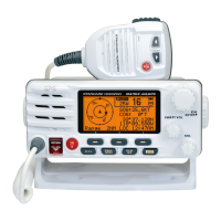
| Brand | Standard Horizon |
|---|---|
| Model | MATRIX AIS/GPS GX2200E |
| Category | Transceiver |
| Language | English |
Step-by-step guide for making a Mayday distress call.
Important safety precautions and RF exposure guidelines for installation.
Instructions for connecting power, antenna, and accessories, including ferrite cores.
Wiring diagrams and pinouts for connecting internal GPS/DSC output to a chart plotter at 4800 baud.
Wiring diagrams for connecting to external GPS/chart plotter at 38400 baud for DSC/AIS.
Wiring diagrams for connecting to external GPS/chart plotter at 4800 baud for GPS data.
Step-by-step guide for installing the optional remote microphone.
Procedures for receiving, transmitting, and managing transmit time-outs.
Using PA/Fog horn modes and operating the intercom system.
Overview of Digital Selective Calling (DSC) and its safety applications.
Explanation of MMSI numbers and programming for DSC functions.
Steps for transmitting, receiving, pausing, and canceling DSC distress calls.
Procedures for transmitting and receiving All Ships urgency or safety calls.
Setting up directories, calls, replies, acknowledgments, and ringers for individual calls.
Programming and managing group MMSI numbers for group calls.
Configuring position request replies and transmitting/receiving requests.
Sending/receiving position reports and navigating to reported positions.
Manually entering latitude and longitude when GPS reception is limited.
Setting up and managing automatic position requests for tracked stations.
Performing DSC test calls to verify radio functions.
Transmitting and receiving polling calls to track vessels.
Storing and managing individual contact information for DSC calls.
Configuring automatic or manual responses to individual DSC calls.
Programming and managing group MMSI numbers for group calls.
Configuring automatic or manual sending of vessel position when requested.
Setting the time interval for automatic position requests between stations.
Overview of the Automatic Identification System (AIS) and its purpose.
Displaying and identifying AIS targets, including SART signals.
Initiating DSC individual calls to detected AIS targets.
Procedure for receiving and responding to AIS-SART distress signals.
Setting the Closest Point of Approach (CPA) alarm distance.
Setting the Time to Closest Point of Approach (TCPA) alarm time.
Marking and saving the current vessel position as a waypoint.
Manually entering vessel latitude and longitude for DSC or report calls.
Guide to diagnosing and resolving common transceiver symptoms and issues.
Resetting all settings and memories to factory defaults.