BR67 User Manual | 11
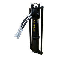
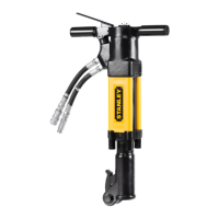
What is the BR67 Hydraulic Breaker?
BR67 is a hydraulic breaker for use in the 70-90 lbs. weight class. It is highly
productive in utility construction, street maintenance, repair of water and
gas mains, and general contracting jobs. BR67 requires an external hydraulic
power source capable of supplying 7-9 GPM.
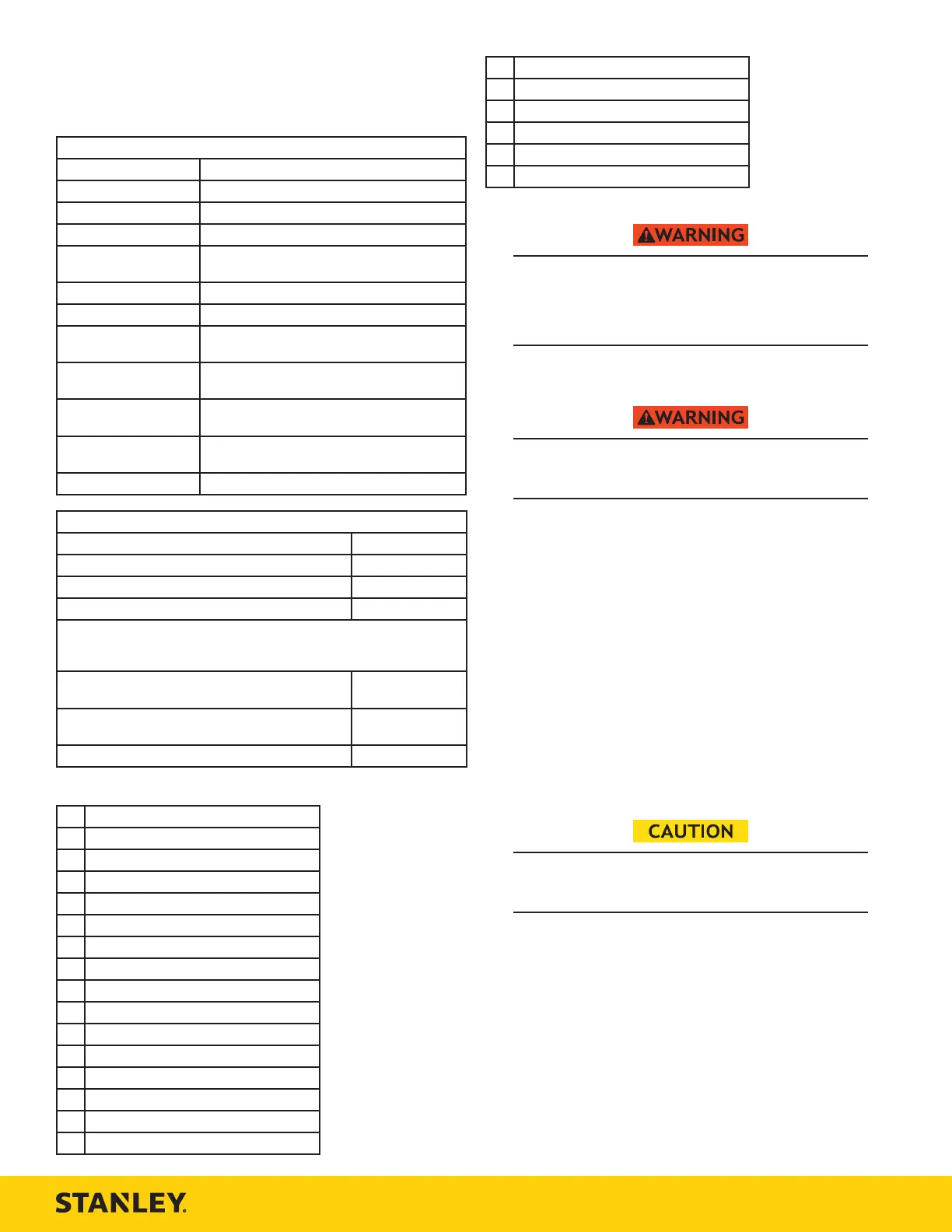
Specifications
Pressure 1500-2500 PSI (103-172 BAR)
Flow 7-9 GPM (26-34 LPM)
Max. Pressure 2500 PSI (172 BAR)
Max. Relief Pressure 2150 PSI (148 BAR)
Recommended Back
Pressure
250 PSI (17 BAR) or less - Can be used with
higher back pressures with reduced seal life.
Couplers 3/8 Inch Male Pipe Hose Ends
Port Size -8 SAE O-ring
Tool Weight T-Handle: 67 Lbs (30 Kg)
Anti-Vibration: 75 Lbs (34 Kg)
Tool Length T-Handle: 29 Inches (74 cm)
Anti-Vibration: 27 Inches (69 cm)
Width (at handles) T-Handle: 16 Inches (41 cm)
Anti-Vibration: 18 Inches (46 cm)
Max. Hydraulic Oil
Temp.
140°F (60°C)
HTMA/EHTMA Category Type II, Category D
Sound & Vibration Declaration
Measured A-Weighted sound power level 103 dBA
Uncertainty 1.7 dBA
Measured A-Weighted Sound Pressure 99 dBA
Uncertainty 3 dBA
Values determined according to noise test code given in ISO 15744, using
the basic standard ISO3744. Test conducted by independent notified body
to comply with 2000/14/EC:2005.
Measured Vibration Emission Value: 3-Axis (Trigger
Handle)
7.7 m/sec ²
Measured Vibration Emission Value: 3-Axis (Non-
Trigger Handle)
7.2 m/sec ²
Uncertainty 1.46 m/sec ²
Parts of a BR67 - Detail A
1
Accumulator Valve Cap
2
Trigger
3
Handle
4
Hydraulic Supply Ports
5
Accumulator
6
STANLEY Logo Decal
7
Breaker Foot
8
Breaker Foot Latch
9
Trigger
10
Trigger Lock
11
Accumulator
12
Handle
13
Hydraulic Supply Ports
14
Type “D” Decal (CE Models)
15
STANLEY Logo Decal
16
Hex Shank Length Decal
17
Breaker Foot
18
Breaker Foot Latch
19
Composite Safety Decal
20
Sound Power Level Decal
21
CE Decal
22
Accumulator Valve Cap
Tool Setup - Detail B
Do not install or change tool accessories while the
hydraulic power source is connected. Accidental
engagement of the tool can cause serious injury.
Disconnect the hydraulic power source before installing
or changing accessories.
1. Disconnect the tool from the hydraulic power source.
Install the Breaker Bit
The tool bit can get extremely hot during operation.
Always wear gloves when installing bits. Hot bits can
cause burns.
2. Unlock the breaker foot latch.
3. Insert the tool bit and lock the latch. Never use BR67 unless the tool bit
is locked in the retainer.
Note: Never use a blunt tool bit as they cause more vibration.
Connect to a Hydraulic Power Source
4. Using a calibrated flow and pressure gauge, check the output of the
hydraulic power source. Ensure it matches the flow and pressure in
“Specifications” on page 11. Hydraulic fluid must be 50°F or above.
Preheat if necessary.
5. Ensure that the hydraulic power source is equipped with a relief valve
set to open at the maximum relief pressure. See “Specifications” on
page 11.
6. Wipe hose couplers with a clean, lint free cloth.
7. Connect the return hose to the tool port marked “Out”.
8. Connect the pressure hose to the tool port marked “In”.
9. Ensure couplers are undamaged, properly connected and are tight.
10. Power up the hydraulic power source.
Tool Operation - Detail C
Always hold tool with both hands to maximize control.
Apply proper down pressure and maintain proper
footing at all times.
1. Wrap your hands around the handles. Stand in back of the tool, using
your leg against the snap-on filler for stability.
Note: Hold the tool correctly and be ready to counteract normal or sudden
movements. Have both hands available.
2. Place the breaker bit on the material to be broken, at a 90° angle.
Apply down pressure.
3. Flip the trigger lock (CE models only).
4. Slowly squeeze the trigger to start breaking. Squeeze harder for fast
speed operation.
5. When starting, break until the tool bit breaks through, then reposition
the bit. Do not use the tool bit as a lever to move material.
Note: Never cool a hot tool bit in water. Tools can become brittle and fail.
6. Continue breaking around the original hole, in 2 inch sized bites.
7. Release Trigger to stop the tool.
Note: If you encounter a breakdown or the tool stops for any reason, release
the trigger and power down the hydraulic power source.
 Loading...