25
range until satisfactory resolution is obtained.
Measuring Resistance
1. Connect the black test lead to the "COM" terminal and the red test
lead to the "
" terminal.
2. Set the range switch to Ω position.
3. Connect test leads across the object to be measured.
4. Read the output on the display.
Note:
1. For measurements > 1MΩ, the meter may take a few seconds to
stabilize reading. This is normal for high resistance measurements.
2. When the input is not connected, i.e. at open circuit, "OL" will be
displayed as overrange indication.
3. Before measurement, disconnect all power to the circuit to be tested
and discharge all capacitors thoroughly.
Continuity Test
1. Connect the black test lead to the "COM" terminal and the red test
lead to the "
" terminal.
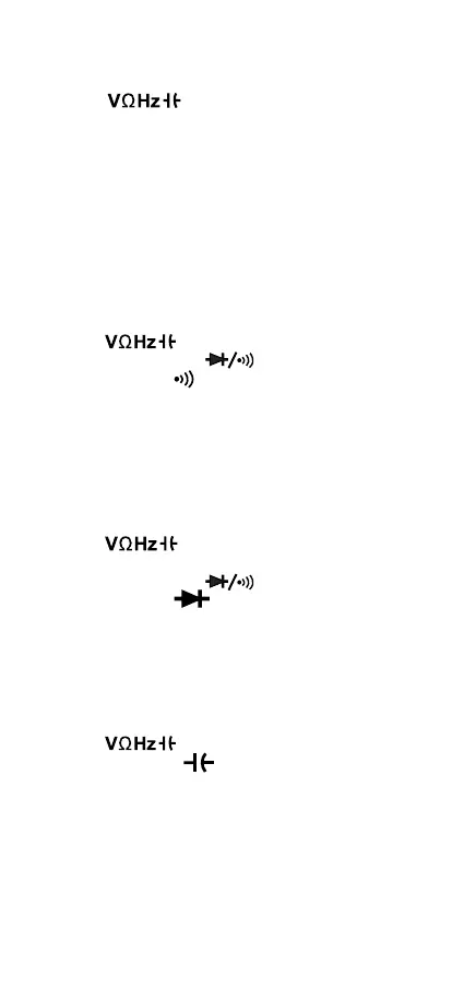
2. Set the range switch to "
" position, then press the "S"
button until the symbol "
" appears on the display.
3. Connect the test leads to the circuit to be measured.
4. If the circuit resistance is less than about 30Ω, the built-in buzzer will
sound.
Note: Before test, disconnect all power to the circuit to be tested and
discharge all capacitors thoroughly.
Diode Test
1. Connect the black test lead to the "COM" terminal and the red test
lead to the "
" terminal. (Note: The polarity of the red lead
is positive "+")
2. Set the range switch to "
" position, then press the "S"
button until the symbol "
" appears on the display.
3. Connect the red test lead to the anode of the diode to be tested and
the black test lead to the cathode of the diode.
4. The display shows the approximate forward voltage drop of the
diode. If the connection is reversed, "OL" will be shown on the display.
Measuring Capacitance
1. Connect the black test lead to the "COM" terminal and the red test
lead to the "
" terminal.
1. Set the range switch to
position.
3. If the display doesn’t read zero, press the "REL" button.
4. Connect the test leads across the capacitor to be measured.
5. Wait until the reading is stable, then read the output on the display.
(For high capacitance measurements, it may take about 30 seconds
for reading to stabilize.)
Note: Before measurement, make sure that the capacitor to be
measured has been discharged thoroughly.
 Loading...