14
ENGLISH
1 Instruction manual
1 Li-Ion battery pack**
1 Li-Ion battery charger**
**Included with SFMCPS620M1 Only
• Check for damage to the tool, parts or accessories which may
have occurred duringtransport.
• Take the time to thoroughly read and understand this manual
prior tooperation.
Markings on Tool
The following pictograms are shown on the tool:
Read instruction manual beforeuse.
Wear eyeprotection.
Wear earprotection.
Do not leave inrain.
Wear headprotection.
Wear protective gloves.
Cut hazard. Keep fingers away from slot.
Wear protective footwear.
Rotational direction of the sawchain.
Electrocution hazard. Keep at least 10 m away from
overhead lines.
Switch the tool off. Before performing any maintenance
on the tool, remove the battery from thetool.
Directive 2000/14/EC guaranteed sound power.
Keep bystanders away.
Keep bystanders away.
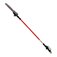
Description (Fig. A)
WARNING: Never modify the power tool or any part of it.
Damage or personal injury couldresult.
1
Handle assembly
2
Center extension pole
3
Saw head assembly
4
Trigger switch
5
Lock button
6
Battery
7
Foam gripper
8
Threaded pole
9
Threaded sleeve
10
Bar clamp
11
Sprocket cover
12
Hex head screws
13
Guide bar
14
Saw chain
15
Scabbard
16
Hex wrench
17
Oil bottle
18
Branch removal hook
Intended Use
This pole saw is ideal for pruning applications and cutting limbs
up to 203 mm indiameter.
DO NOT use under wet conditions or in the presence of
flammable liquids orgases.
This pole saw is a professional power tool.
DO NOT let children come into contact with the tool.
Supervision is required when inexperienced operators use
thistool.
• Young children and the infirm. This appliance is not
intended for use by young children or infirm persons
without supervision.
• This product is not intended for use by persons (including
children) suffering from diminished physical, sensory or
mental abilities; lack of experience, knowledge or skills
unless they are supervised by a person responsible for their
safety. Children should never be left alone with thisproduct.
ASSEMBLY AND ADJUSTMENTS
WARNING: To reduce the risk of serious personal
injury, turn tool off and disconnect battery pack
before making any adjustments or removing/
installing attachments or accessories. An accidental
start-up can causeinjury.
WARNING:Use only STANLEYFATMAX battery packs
andchargers.
Inserting and Removing the Battery Pack
from the Tool (Fig. B)
NOTE: Make sure your battery pack
6
is fullycharged.
To Install the Battery Pack into the Tool Handle
1. Align the battery pack
6
with the rails inside the tool’s
handle (Fig. B).
2. Slide it into the handle until the battery pack is firmly seated
in the tool and ensure that you hear the lock snap intoplace.
To Remove the Battery Pack from the Tool
1. Press the release button
24
and firmly pull the battery pack
out of the toolhandle.
2. Insert battery pack into the charger as described in the
charger section of thismanual.
Fuel Gauge Battery Packs (Fig. B)
Some STANLEYFATMAX battery packs include a fuel gauge
which consists of three green LED lights that indicate the level of
charge remaining in the batterypack.
To actuate the fuel gauge, press and hold the fuel gauge
button
27
. A combination of the three green LED lights will
illuminate designating the level of charge left. When the level of
charge in the battery is below the usable limit, the fuel gauge
will not illuminate and the battery will need to berecharged.
 Loading...