11
At times it may be neccessary to reset the controller. This
could happen if a fault occurs in the controller. For ex-
ample, excessive engine speed. If a fault does occur the
power unit will return to an idle and the operator will have
no control of the unit. To reset the controller, simply turn off
the power unit and restart it.
USING THE 110 VOLT AC OUTLET
The 110 volt AC outlet is only found on specifi c models with
the Briggs & Stratton engine.
The POWELINK™ system output remains 110 volts
throughout the entire engine speed range. Output wattage
increases with engine speed.
To use the 110 volt AC feature, turn the AC control switch to
the ON position. The 110 volt outlet can also be used while
in the 8 gpm mode, but is disabled when the fl ow control
switch is set to the 5 gpm mode.
See included POWERLINK™ On-Board Generator System
Manual for details.
USING THE 12 VOLT DC OUTLET
A 12 VDC outlet is on specifi c models. The DC outlet is ON
at all times.
STARTUP
Before starting the engine make sure the fl ow selector
switch is in the OFF position.
Note:
The power unit will not start if the fl ow control switch is
not in the "OFF" position.
Pull choke knob out and move the Throttle Control Switch
to the auto-idle-off or the auto-idle-on position, whichever
mode of operation the operator prefers. Ensure the fl ow
selector switch is in the OFF position.
On power units equipped with the POWERLINK™ feature,
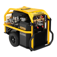
CONTROLS
This unit is equipped with an advanced proportional engine
control system. It provides a means of controlling engine
speed by adjusting the fuel control lever with an actuator.
The Power Unit provides one circuit, with an oil fl ow of 5
gpm/19 lpm up to 2000 psi/140 bar or 8 gpm/30 lpm up
to 2000 psi/140 bar with a factory-programmed electronic
governed engine throttle.
Figure 3. Panel Control Valve
One hydraulic tool can be connected to the tool circuit.
The circuit is activated by turning the fl ow control switch to
either the 5 gpm/19 lpm or 8 gpm/30 lpm setting.
THROTTLE CONTROL
The throttle control permits the operator to select one of 2
operating modes after the engine has warmed up. When
starting the engine, make sure the fl ow selector switch is in
the OFF position. The throttle control switch can be set in
either the AUTO-IDLE-ON or AUTO-IDLE-OFF positions.
AUTO-ON
When the throttle control switch is in the "AUTO-ON" posi-
tion, the oil fl ow is regulated automatically when the trigger
on the tool activated. When the tool is not being used the
engine will return to idle automatically, after a 10 second
delay.
This setting will produce 5 gpm/19 lpm or 8 gpm/30 lpm
depending on which postion the operator has selected with
the fl ow selector switch.
AUTO-OFF
When the throttle control switch is in the "AUTO-OFF" posi-
tion, the engine speed is held to maintain 5 gpm/19 lpm or
8 gpm/30 lpm depending on which position the operator
has selected with the fl ow selector switch. When a tool is
not being used the engine will not return to idle until either
the fl ow selector switch is turned to the OFF position or the
throttle control switch is turned to AUTO-ON.
Note:
It may be necessary to reset the Controller.
OPERATION
IGNITION SWITCH
FLOW SELECTOR
SWITCH
THROTTLE CONTROL
SWITCH
AC CONTROL
SWITCH
The accessories (if left on) that are
plugged into this outlet could drain the bat-
tery.
IMPORTANT
 Loading...