11
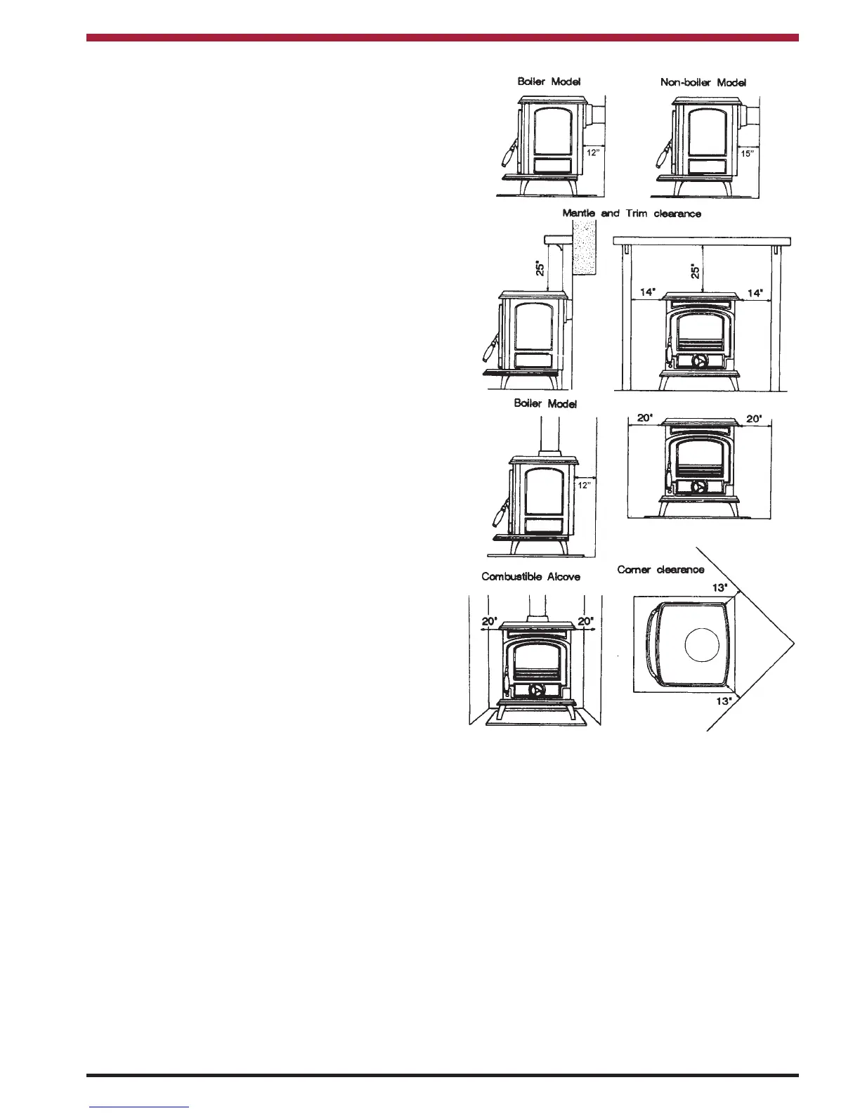
CLEARANCE TO COMBUSTIBLES
Maintain at least the following clearances to all
combustible material:
Side wall to stove 20” 510mm
Back wall to stove non-boiler model 15” 380mm
Back wall to stove boiler model 12” 305mm
Ceiling to horizontal connector 18” 460mm
Corner 13” 330mm
Mantle clearance 25” 635mm
Side trim, which extends less than 2”
from the face of the fireplace 14” 355mm
It is recommended that this appliance is sited next to
and on a non-combustible surface. A minimum all
round clearance of 100 mm will allow air circulation
and not impede the performance of the stove.
Fig.8
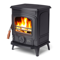
LOCATION
There are several conditions to be considered in
selecting a location for your Stanley Oisin Stove.
a. Position in the area to be heated, central
locations are usually best.
b. Allowances for proper clearances to
combustibles.
c. Allowances for proper clearances for
maintenance work.
The connector may pass through walls or partitions
constructed of combustible materials provided the
connector is either listed for wall pass-through or is
routed through a device listed for a wall pass-
through and is installed in accordance with the con-
ditions of the listing. Any unexposed metal that is
used as part of a wall pass-through system is
exposed to flue gases shall be constructed of stain-
less steel or other equivalent material that will resist
corrosion, softening, or cracking from flue gas at
temperatures up to 982
o
C.
FLOOR PROTECTION
It is recommended that this appliance is installed on
a solid, level, non combustible hearth conforming to
current Building Regulations.
When installing this heater on a combustible floor , a
floor protector, consisting of a layer of non-com-
bustible material at least 3/8” thick or 1/4” thick cov-
ered with 1/8” sheet metal is required to cover the
area under the heater and extend to at least 18” at
the front and 8” to the sides and rear. This will pro-
vide protection from sparks and embers which may
fall out from the door when stoking or fuelling. (See
Fig.9)

 Loading...