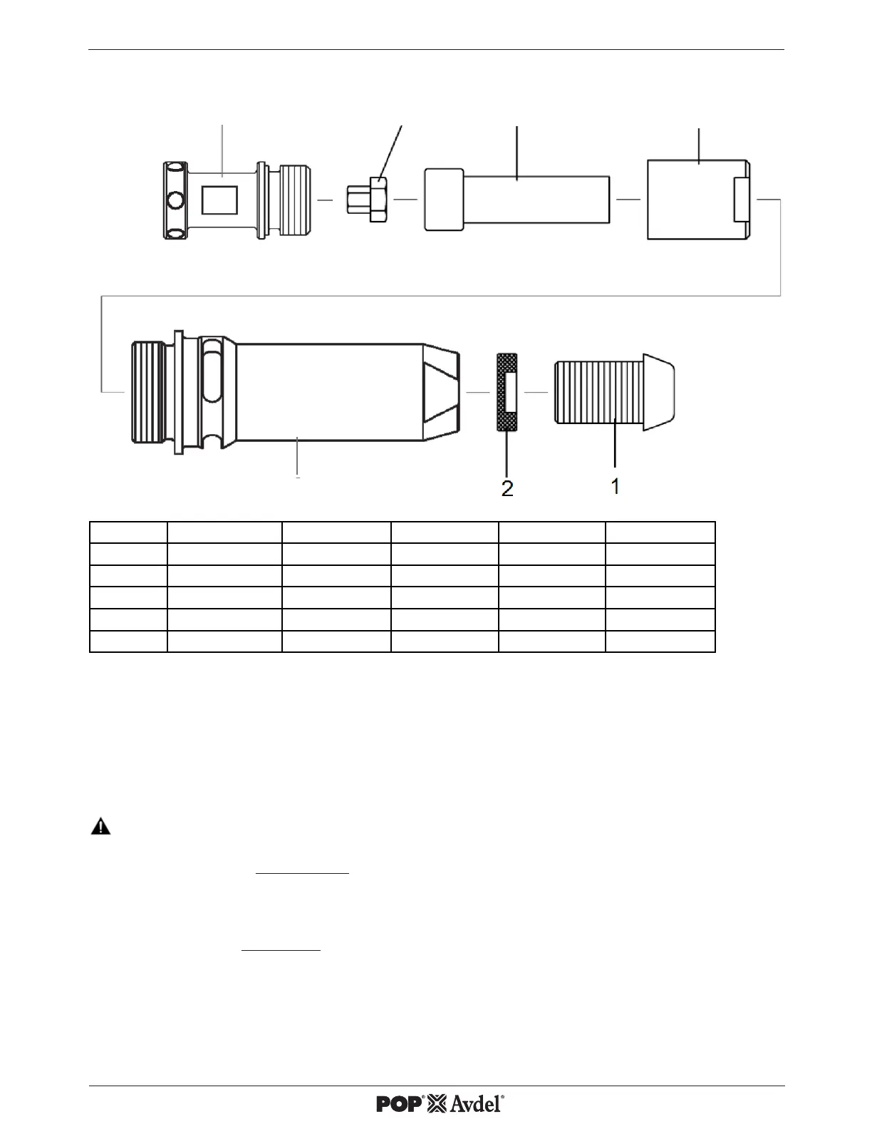
Blind Stud Nose Equipment
* Reducing Sleeve (Fig. 2 Nr. 7) replaces Chuck Nut ( Fig.1 Nr. 5) tted to Base Tool.
** Nose Assembly includes special Nose Casing 07555-00315. The standard Nose Casing tted to the Base
Tool is not used for this type of M10 Nose Assembly.
All Nose Asemblies also include a Nose Tip Nut 2 (part number 07555-00901)
Fitting Instructions
t IMPORTANT Air supply must be disconnected from the tool before working on the nose assembly.
For disassemby please see Fig. 1 Page 2. Item numbers in bold refer to components in that drawing
t Remove the Nose Casing 4 and the Chuck Nut 5 tted to the base tool. Retain Nose Casing 4.
For assembly please see Fig.2 above. Item numbers in bold refer to components in this drawing.
t Fit Drive Nut 3 onto Drive Shaft 6 and insert into Reducing Sleeve 7.
t Screw Reducing Sleeve 7 onto Mandrel Adaptor 8.
t Screw on the Nose Casing 4 and Nose Tip 1 with the Nose Tip Lock Nut 2.
t The reverse operation is carried out for equipment removal.
Fig. 2
6 73

 Loading...