5
Wireless Tag Reader Installation Guide
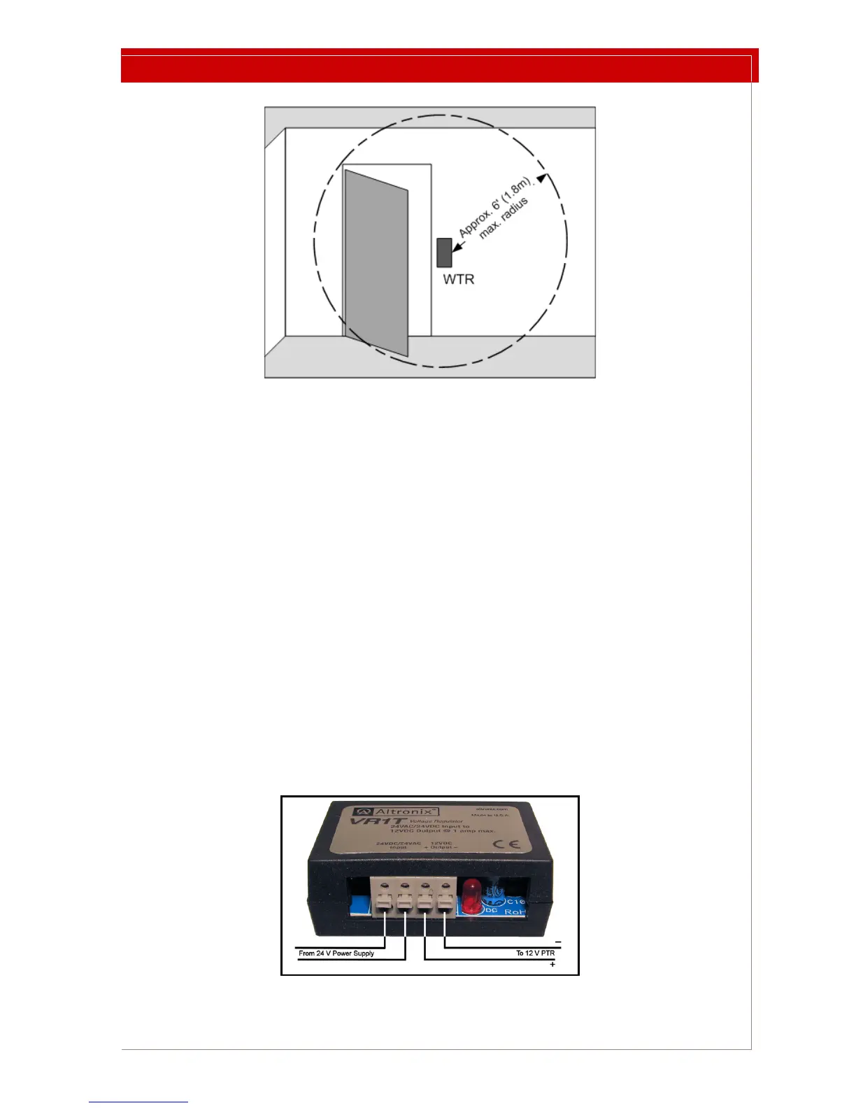
Figure 2: WTR Mounted Beside a Door to Illustrate Maximum LF Field
The LF detection field is approximately spherical and has a maximum 6 ft. (1.8 m)
radius.
The range remains the same regardless of the WTR’s physical orientation.
The LF Field radius can be varied as described in “Setting the LF Field Strength” on
page 8.
To install the WTR:
1 Select a mounting location remembering that the detection zone is limited.
2 Use the WTR backplate as a template for locating mounting
holes. The WTR
backplate has been designed to accept a #6 screw. Use mounting hardware
that allows the device to be removed and then replaced in the same location.
3 The hole for the power wire is in line with the two mounting holes, and is 0.75
in. (3 cm) from the nearest mounting hole.
4 Drill a hole in the wall for the power wire.
5 Choose, route, and install a power wire according to your local wiring
re
gulations and applicable legislation.
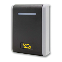
6 If you are supplying 24V power, wire the included power converter to the
supply and mount the co
nverter in the wall with the supplied velcro strips.
Figure 3: Power Converter