6
Wireless Tag Reader Installation Guide
7 Open the WTR using a Number 1 Phillips screwdriver to remove the 4 screws.
8 Note the settings on the two red DIP switches, but do
NOT adjust them.
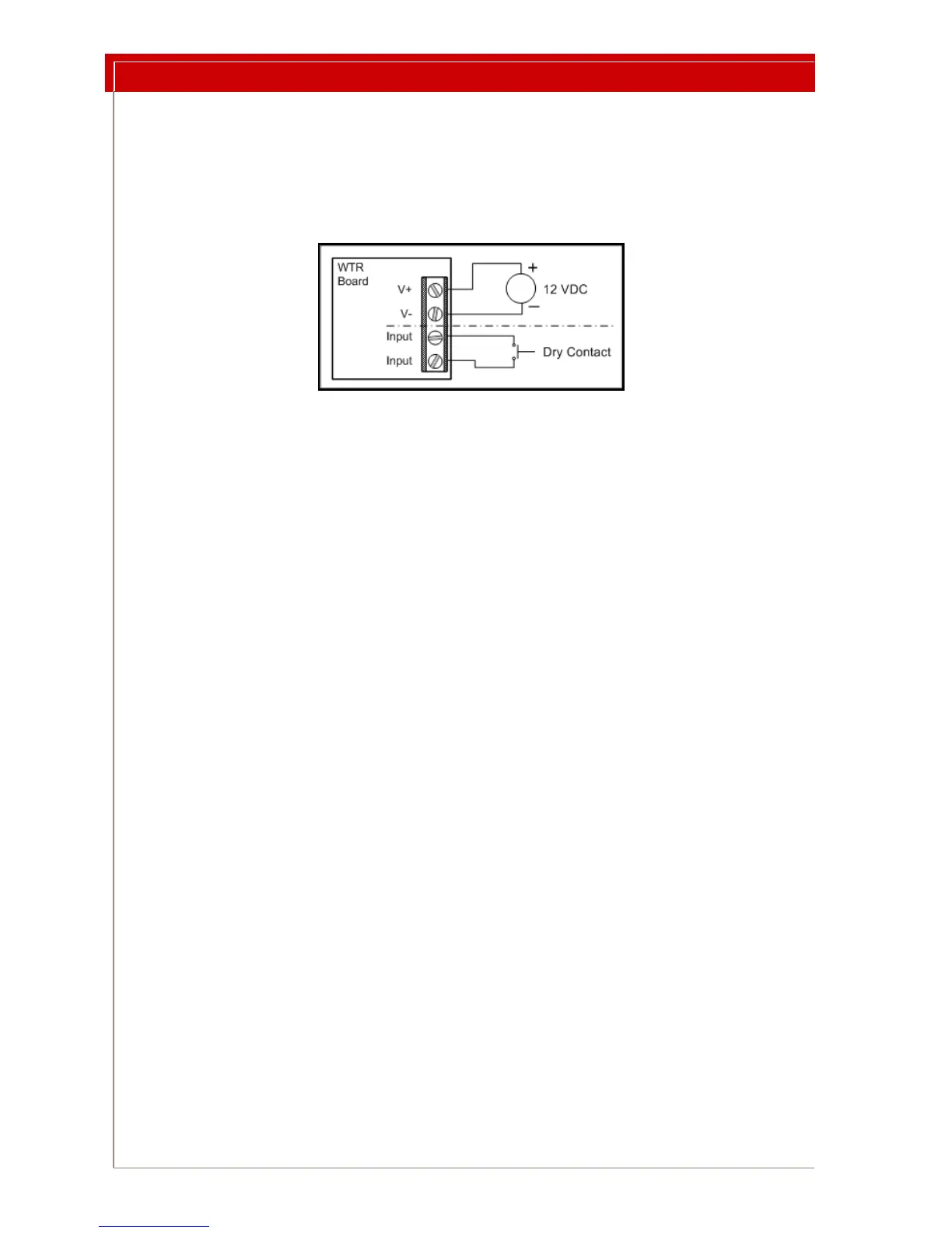
9 Push the power wire through the WTR backplate and work it towards the
wir
ing connector. Connect the power wires as in Figure 4. See Figure 5 on
page 7 for terminal block location and orientation.
Figure 4: 4 Pin Terminal Block Wiring
10 Optionally, connect the
dry contact input wires as shown in Figure 4.
11 Temporarily mount the WTR in its final location. Do not close the case.
12 Configure the WTR:
12.a Adjust the LF Field. See “Setting the LF Field Strength” on page 8. This
step must be done while the WTR is in Test
Mode.
12.b Set the normal operating mode. See “Selecting the Operating Mode”
on page 9.
12.c Set the WTR address. See “Setting the WTR Address” on page 11.
12.d Set the indicators. See “Setting Indicator LEDs and Buzzer” on page 11.
13 Record the WTR address and location.
14 Make sure the red DIP switches still retain the
settings you noted in Step 8.
15 Make sure that switches 4 and 5 on the Options switch block are
OFF.
16 Remove the WTR from the wall and close the case, orienting the case so that
th
e LEDs are underneath the light holes.
17 Using the holes provided in the backplate, mount the WTR in its location.