75
Operating mode S1 (continuous operation)
The machine can be continuously operated with the
quoted power output.
Operating mode S2 (temporary operation)
The machine may be temporarily operated with the
quoted power output. Afterwards the machine must be
stopped for a while to prevent it from overheating
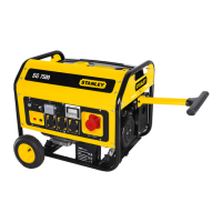
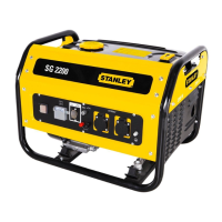
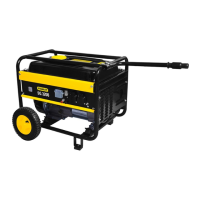
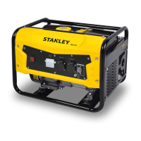
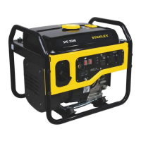
5. Layout (Fig. 1-7)
1 Tank indicator
2 Fuel cap
3 230 V~ socket-outlets
4 400 V~ socket outlets
5 12 V d.c. outlet
6 Earth connection
7 Overload cut-out
8 Voltmeter
9 Oil drain plug
10 Oil ller plug
11 Oil shortage cut-out
13 Choke lever
14 Pull cord
15 Electro starter
16 Petrol cock
17 Wheels
18 Carry handle
19 Rubber feet
20 Battery
21 Transport handles
22 Oil ller set
23Spark plug wrench set
24 Push bar assembling set
25 Wheel assembling set
26 Spanner
27 DC oulet adapter cable
28 Air lter set
29 Spark plug
30 Mufer
31 230 V~ / 400V ~transfer switch
32 Transport handle xing knob
33 Electro starter key
6. Before putting the machine into operation
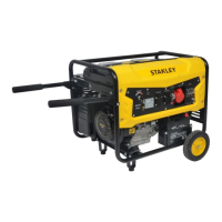
6.1 Wheel assembly (g 3-5)
1. First place one end of the bolt (item 25) through the
hole in the frame and secure it with a nut and washer.
2. Put the socket through the another end of bolt (item
25) and place the wheel, washer and secure it with the
nut.
3. Place the wheel cover and secure it via clip as
designed on the inner side of cover.
4. Assemble the left side wheel with same prodcedure
as above.
Important:
The inner wheel should be inated for it has been
shipped out with lower pressure (max. gauge pressure 3
bar/0.3 MPa).
6.2 Rubber feet assembly (g. 6)
Hold the foot (item 19) against the frame as shown. First
place the bolt through the hole in the frame and the hole
in the foot and secure it with a nut. Then secure other
three bolts and nuts with same procedure.
6.3 Transport handle assembly (g. 7-8)
Place the carry handle (item 18) through the bracket
and xing it with knob (item 32). Then place the bolt
with a gasket through the hole in the frame and the push
bar. And secure it with a washer and a nut, as shown in
Figure 12-13).
The user can adjust the position of carry handle for
removing the machine via release the knob (item 32) and
rotated the carry handle (item 18) to horizontal position.
6.4 Electrical safety
- Electric supply cables and connected equipment must
be in perfect condition.
- The generator is to be operated only with equipment
whose voltage specications conform to the generator's
G
B