FT5X User Guide www.microdata.fi support@microdata.fi
2. INSTALLATION INSTRUCTION
2.1 Interface Description
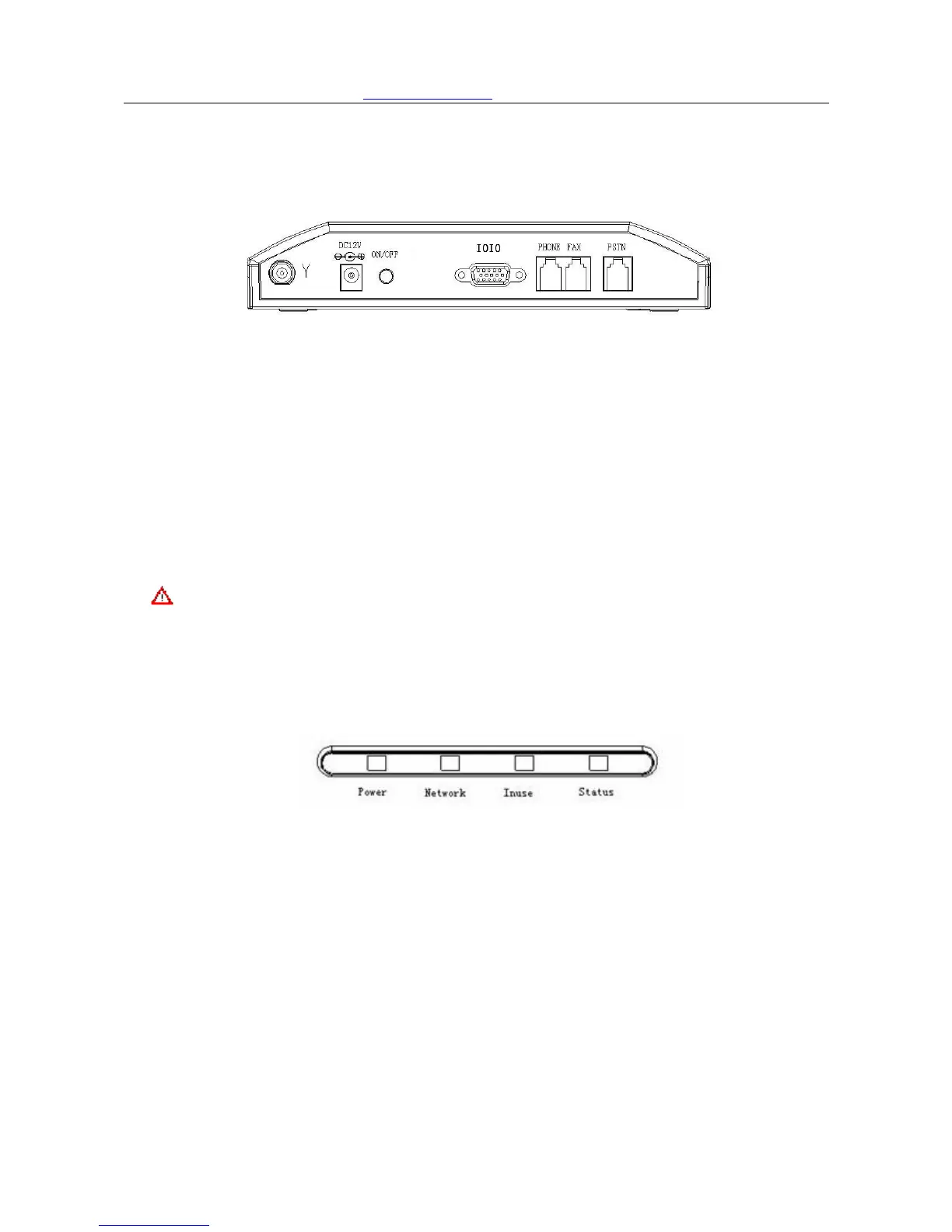
FT5X Back plane
FT5X Back plane interface description:
Y ……… Antenna port
DC 12V………Power supply
ON/OFF……… Power switch
IOIO ………… RS232 Serial Port
PHONE ………Phone port, connect to the regular phone
FAX…………… FAX port, connect to the regular fax machine
PSTN………… External line port,connect to the external phone line
Caution: Do NOT plug external line into Telephone socket, or it may cause device
damage.
2.2 Indicators
Indicators
There are 4 indicators on the front panel of fixed wireless terminal, functioning as follows:
Slow flash defines: Flash once per second to indicate
Quick flash defines:Flash 10 times per second to indicate
Dark defines:Indicating device not powered on or starting up. The STATUS indicator is
still OFF within 15 seconds when turn on the device, and then the indicator becomes
slowly flashing.
Indicators instruction
1、 Power:Power supply indicator; two color indicator
1) Green:external power supply;
2) Red:battery supply;
3) Dark:no power supply;
4/31