This document describes the Shallow Well Jet Pump, specifically models ES05S, EK05S, CPH05S, ES07S, EK07S, ES10S, EK10S, and JHU15S. It serves as a comprehensive manual covering installation, operation, maintenance, and troubleshooting.
Function Description
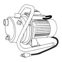
The Shallow Well Jet Pump is designed to draw water from a source where the suction lift is 25 feet or less. It can be used with various water sources including drilled (cased) wells, dug wells, driven wells, cisterns, or lakes. The pump's primary function is to move water from these sources to a pressure tank and then to a house plumbing system, providing a reliable water supply. It is crucial for the entire system to be air and water tight for efficient operation and to maintain prime.
Important Technical Specifications
The manual provides a MOTOR DATA CHART detailing the electrical specifications for different pump models and horsepower ratings:
- CPH05S (1/2 HP): 1 phase, 115 or 230 Volts, Max Amps 13.0/6.5, Locked Rotor Amps 36.0/18.0.
- All others (1/2 HP): 1 phase, 115 or 230 Volts, Max Amps 8.6/4.3, Locked Rotor Amps 26.0/13.0.
- All (3/4 HP): 1 phase, 115 or 230 Volts, Max Amps 13.0/6.5, Locked Rotor Amps 36.0/18.0.
- All (1 HP): 1 phase, 115 or 230 Volts, Max Amps 14.0/7.0, Locked Rotor Amps 52.0/26.0.
- All (1-1/2 HP): 1 phase, 115 or 230 Volts, Max Amps 21.0/10.5, Locked Rotor Amps 98.0/49.0.
The motor is dual voltage (115V or 230V), with most models pre-wired for 115V at the factory. 230V operation is generally more economical and requires a smaller wire size. The motor specifications for model 98L105 (1/2 HP) include: 1 phase, 60 Hz, 115/230 Volts, S.F. 1.2, Amps 6.4/3.2, S.F. Amps 8.6/4.3, RPM 3450, Type C, Duty Cont., Temp 65C, KVA Code G, Frame 56L, Ins Class B. It is thermally protected automatic and uses copper conductors only.
Suction Lift: The pump is designed for a maximum vertical suction lift of 25 feet.
Horizontal Distance: The horizontal distance between the pump suction and the water source can affect operation; if it exceeds 100 feet, manufacturer assistance is recommended.
Piping: NSF PW Schedule 40 PVC pipe and fittings or galvanized steel are recommended for water pressure applications. DWV fittings are not suitable.
Electrical Wiring: A WIRE SIZE CHART is provided, recommending copper wire and fuse sizes based on distance from motor to meter and horsepower, for both 115V and 230V single-phase motors. For example, a 1/2 HP motor at 0-50 ft requires 14 AWG wire and a 15 Amp fuse for both 115V and 230V. For longer distances or higher HP, larger wire gauges and fuses are necessary.
Usage Features
Installation:
The installation process is detailed, covering connections from the well to the pump, pump to the pressure tank, and tank to the house plumbing.
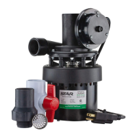
- Well to Pump Connection (Suction Pipe): Requires careful dry-fitting, proper gluing (vertical whenever possible), and sealing of threaded fittings with pipe tape and paste to ensure an air-tight connection. Models JHU10S, EK10S, JHU15S, and CPH05S require attaching an external ejector, while ES05S, EK05S, ES07S, and EK07S have a built-in ejector. A foot valve is required for drilled wells, and a check valve for driven wells, to maintain prime.
- Pump to Pressure Tank Connection (Discharge Pipe): Involves installing a galvanized nipple, tee fitting, and an optional pressure gauge or pipe plug. 1 and 1-1/2 HP models require 1-inch discharge fittings, while others use 3/4-inch. An optional union is recommended for easy connection/disconnection.
- Tank to House Connection: Connects the pressure tank to the house plumbing, typically using a 1-inch inlet elbow, adapter, and pipe, followed by another elbow, reducer bushing, and 3/4-inch pipe. An optional union and shut-off valve can be installed.
Electrical Connections:
- All wiring must be performed by a qualified electrician in accordance with local and national electrical codes.
- The pump must be connected to a dedicated electrical circuit with a circuit breaker.
- Proper wire sizing is critical to prevent motor failure and fire.
- The pump must be securely and adequately grounded.
- The pressure switch is screwed into a 1/4-inch opening on top of the pump. Electrical strain reliefs are used to secure cables. Motor wires connect to inside terminals of the pressure switch, and power supply wires connect to outside terminals. Green ground wires from both the motor and power supply connect to green ground screws on the pressure switch.
- Voltage Change: The pump's dual voltage motor can be reconfigured from 115V to 230V (or vice versa) by changing the position of specific wires on the terminal board, as illustrated in the wiring diagrams. For 230V service, the gray wire moves from the "A" terminal to the "B" terminal space post, and the red wire moves from the "L2" terminal to the "B" terminal space post.
Priming and Startup:
- All pumps must be primed (filled with water) before first operation. This involves removing the priming plug and air relief plug, slowly filling the pump cavity until water comes out of the air relief hole, and then continuing to fill until water reaches the top of the priming plug.
- After priming, the priming plug is re-threaded, and any optional ball valve is opened.
- The breaker is then turned on to start the pump.
- If the pump hums or turns off repeatedly, the power should be shut off immediately, and voltage checked to match the pump's wiring.
- If the pump fails to prime within five minutes, power must be turned off, and all pipe connections checked for leaks. The system must be water and air tight.
- Discharged water should be checked for milky color, which indicates an air leak. Re-priming may be necessary.
Maintenance Features
Troubleshooting:
A detailed troubleshooting guide is provided for common issues:
- Little or no discharge: Could be due to casing not filled, high/long suction lift, air leak, small foot valve, submerged foot valve, incorrect wiring, gasket leak, or closed valves. Solutions include filling casing, moving pump closer to water source, repairing leaks, replacing foot valve, submerging lower, checking wiring, replacing gasket, or opening valves.
- Pump will not deliver water or develop pressure: Possible causes include no priming water, suction line leak, closed discharge line, closed suction line, leaking foot valve, or clogged suction screen. Solutions involve filling casing, repairing leaks, opening ball valve, replacing foot valve, or cleaning screen.
- Loss of suction: Can be caused by air leak, high suction lift, insufficient inlet pressure, or clogged foot valve/strainer. Solutions include repairing leaks, lowering suction lift, increasing inlet pressure, or unclogging.
- Pump vibrates and/or makes excessive noise: May be due to non-rigid mounting, foreign material in pump, damaged impeller, or worn motor bearings. Solutions include reinforcing mounting, disassembling and cleaning pump, replacing impeller, or replacing bearings.
- Pump will not start or run: Could be due to improper wiring, blown fuse/open circuit breaker, loose/broken wiring, foreign object in impeller, shorted motor, or opened thermal overload. Solutions include checking wiring, replacing fuse/breaker, tightening connections, disassembling pump, replacing motor, or allowing unit to cool and determining overload reason.
Care and Maintenance:
- Winterizing: It is crucial to drain the entire system if there is a danger of freezing. A drain plug is provided at the bottom of the pump case for this purpose. This prevents pump damage from freezing weather.
Safety Information:
The manual emphasizes several safety warnings:
- DANGER: Always disconnect power before working on the motor or its connected load to prevent fatal electrical shock. Do not handle the pump with wet hands or while standing in water. These pumps are not investigated for use in swimming pool areas.
- WARNING: Follow all local electrical and safety codes. Replace damaged wiring immediately. Do not kink power cable or allow contact with oil, grease, hot surfaces, or chemicals. Wire motor to correct supply voltage. Unit must be securely and adequately grounded. This product contains chemicals known to cause cancer and reproductive harm. Install a pressure relief valve in the discharge pipe. Release all pressure before working on components. Do not pump flammable or explosive fluids.
- CAUTION: Protect power cable from sharp objects. Exterior of operating motor can be hot. Ensure power source conforms to equipment requirements. Do not run pump dry. Pump and plumbing must be full of water before startup. Do not pump water containing sand, mud, silt, or debris.
Customer service is available Monday through Friday, 7:30 am to 5:00 pm EST, at 1-800-742-5044 for any questions or issues with missing/damaged parts.