7.List of contents
1.
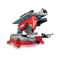
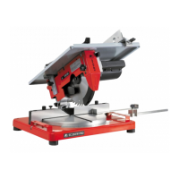
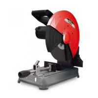
Provided uses
of the machine
2.
Unpackaging
and
assembling
3.Setting
or fastening
the
machine
in
a
stable
position
4.Connection
to
the
grid, wiring,
fuses,
socket
type
for the
jack
and
grounding conditions
5.
Illustrated descriptions
of functions
6.Limitations
regarding environmental conditions
7.List of contents
8.
Settings and testing
9.
Changing
tools
10.
Fixing for
operation
11.
Limits regarding the workpiece
size
12.General instructions
for use
13.
Precautions
and working garment
14.
Special
safety precautions
15.Measures for preventing machine-specific
risks
16.Dust extraction
17.
General
safety
instructions
18.
Regular
cleaning, maintenance and
greasing
1
9.R
e
p
a
ir
se
r
v
ice
by
t
he
m
anufa
cture
r
or
commercial
agent
20.List
of parts
that
may be
replaced
by
the user
21.
Special
tools
as possibly
required
22.
Safe
operation
23.T
echnical
specifications
24.W
arrantee
25.
Declaration
of
conformity
8.Settings and
testing
W
arning!
Before any intervention
on the
electrical tool
remove jack from power
socket.
If
the
machine
has
been
subject
to prolonged
or
intense
use,
it must be checked and adjusted
so
as
to
ensure
the machine's correct quality
of
service
and
safety.
This
requires knowledge,
experience and special
tools. The
official
technical service
of Stayer Iberica
S.A. will carry out
that work
for you in a
quick
thorough and
inexpensive
manner.
Adjusting
the
locking
in the
lower
resting
position
IMAGES
Checking
1.On
starts
from
the
machine being
locked
in
the
upper resting
position.
2.Unlock
by pressing
button
29.
3.Lower down
to
the lower
stop
by means
of 4.
Press button
31
.
If
the bolt of
the button is well
adjusted, it
must enter
until abutting. Otherwise
proceed to
adjusting
ENGLISH
29
29
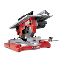
18.Nut for vertical adjustment for fixed mitre angles
at 0º
19.Screw for vertical adjustment for fixed mitre
angles at 0º
20.Nozzle for expelling sawdust
21.Cutting disk
22.Saw blade fastening screw
23.Clamping flange
24.Wing nuts for adjusting the height of the upper
table / fastening the lower guard
25.Upper cutting table
26.Movable guard of the upper table
27.Movable stopper guide of the upper table
28.Wing nut for adjusting the movable stopper
guide of the upper table
29.Locking button for the upper resting position
30.Locking button for the tiltable guard hood
31.Locking button for the lower resting position
32.Counterweight spring for the cutting head
33.Adjustment cam for the indicator for horizontal
angles
34.Stationary lower guard
35.Nut for retaining the adjustment of the locking in
the lower position
36.Screw for adjusting the locking in the lower
position
37.Keel of the upper table
38.Lock for the guard of the upper table
39.Fastening screw for the adjusting system for
fixed-length cutting
40.Fastening wedge of the adjusting system for
fixed-length cutting
41.Support for the adjusting system for fixed-length
cutting
42.Adjustable stopper of the adjusting system for
fixed-length cutting
43.Adjusting wing nut for the movable stopper
guide of the upper table
44.Insertion hollow of the system for fixed-length
cutting
45.Cutting length scale of the upper table
46.Keel height adjusting screw
47.Brush-holder lid
48.Fastening screw for the brush-holder cover
49.Brush-holder
50.Brush-holder connecting screw
51.Brush pressing spring
52.Brush
53.Horizontal head movement button.
54.Adjustment screws crankcase.
55.Cover fixing bolts of the keel top table.
56.Cover top table keel.
6 . L i m i t a t i o n s r e g a r d i n g
environmental conditions
The IP degree of this machine is 20. This machine is
protected against its dangerous parts being
accessed by a finger and against solid foreign
particles having diameters of 12'5 mm and more.
This machine does not have any kind of protection
against the entry of water so that its use in exterior
or interior environmental conditions with a risk of
precipitations is forbidden.
A C
 Loading...