Installation 2.11 2100 Series
INSTALLER'S FINAL CHECK-OUT PROCEDURE
With the heater de-energized, hinge the right side panel open
(Page A.08). Complete the system check-out below:
Step 1 Inspect all eld connections to ensure they are tight and
that all wires are routed correctly.
Class II (low voltage) wiring or any wiring not rated
for line voltage should never be installed in a line
voltage area.
Step 2 Check the damper system to ensure the damper operates
freely and that there is no debris in this area, which could
inhibit its operation. To do so, slowly press the damper
lever extending from the damper downward. Be careful
not to bend the damper actuator. If the damper is not
free, remove the blower and clean any debris from the
damper.
Step 3 Make sure the blower operates by adjusting room
temperature set point above the actual room temperature.
Step 4 With the system in an off-peak (charge) mode, initiate
the charge control override (Page 1.03).
Step 5 Check for proper amperage draw on the charging
circuit(s). Use the Charge Circuit Amperage Draw Chart for reference to the correct amperage of the
specic heater being installed.
Step 6 Verify that the heater receives and responds to the utility peak control device and that all other system
controls are operating properly.
Step 7 Place grill slats in position, if removed.
Grill slats should bow up to direct
airow up, away from the oor.
Step 8 Place the right side panel back into
position and secure.
Step 9 Return the control circuit board to its
original position and install the painted
front panel.
Step 10 Verify that conguration settings are
correct for the application. Refer to the
Conguration Menu (Page 2.10).
On start-up, odors and/or small
volumes of smoke relating to
rst time operation of the heating
components may occur.
Step 11 Make certain all fuses and/or circuit
breakers are labeled in the distribution
service panel as this system may be connected to more than one branch circuit.
Step 12 Present owner with the manual and warranty information. The owner's registration card must be
completed and returned to Steffes Corporation to ensure warranty coverage. The owner should retain
the top portion of the card for their records.
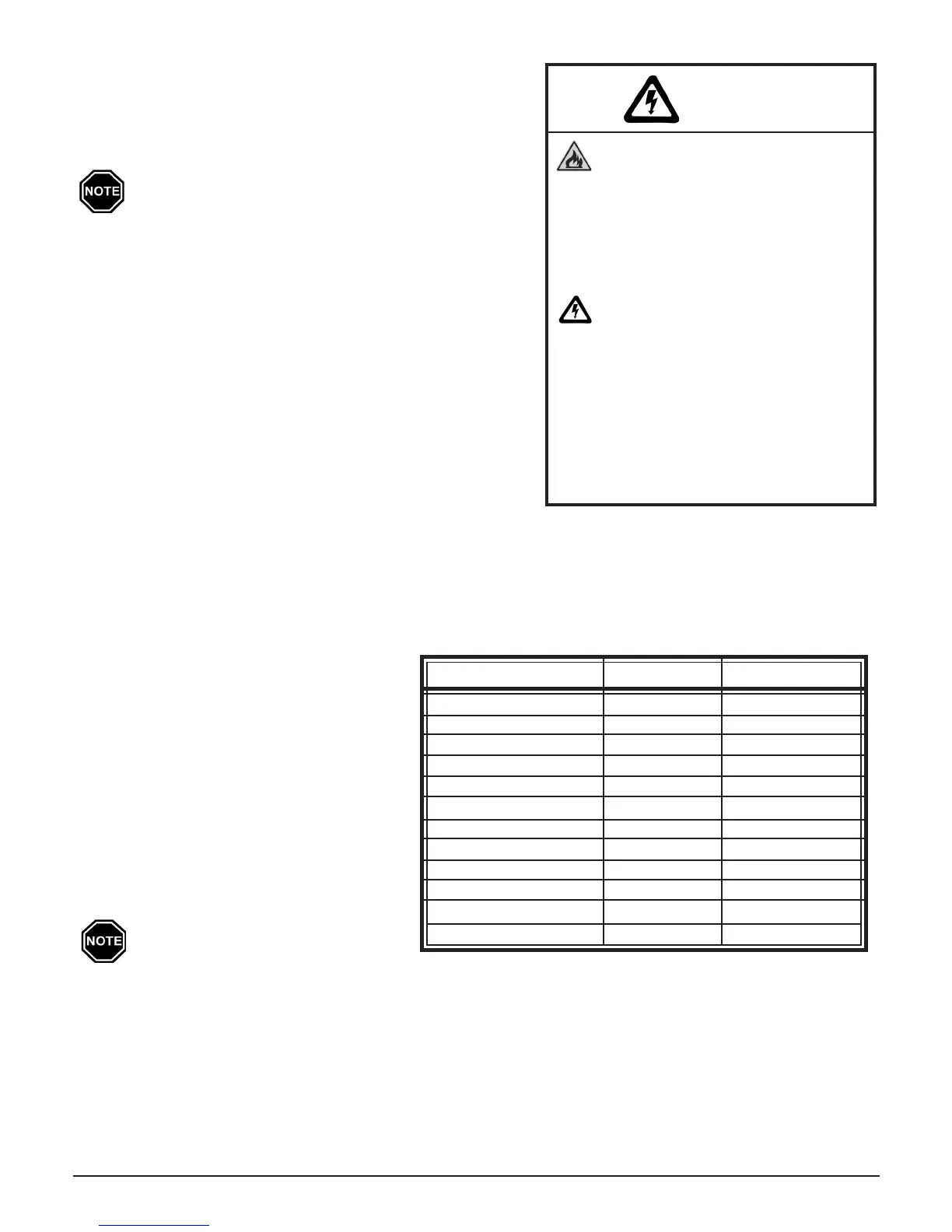
INPUT WATTAGE VOLTAGE AMP DRAW
1.32 kW 120 11.00
2.4 kW 240 10.00
3.0 kW 240 12.50
3.6 kW 240 15.00
4.5 kW 240 18.75
4.8 kW 240 20.00
5.4 kW 240 22.50
6.0 kW 240 25.00
7.2 kW 240 30.00
7.5 kW 240 31.25
9.0 kW 240 37.50
10.8 kW 240 45.00
CHARGE CIRCUIT AMPERAGE DRAW CHART
(AMP draw is calculated by taking the total input wattage
divided by the input voltage. Allow +/- 5% tolerance at
nominal input voltage.)
WARNING
Riskofre.Cancauseinjury
or death. ETS devices run
for long periods of time at
high electrical loads. Poor
or marginal connections will
cause the connections to
overheat and fail.
Risk of electric shock. Can
cause injury or death. This
heater may be connected to
more than one branch circuit.
Disconnect power to all circuits
before installing or servicing.
DO NOT remove the painted
front panel while energized.
Equipment must be serviced by a
qualiedtechnician.