Appendix A.04 2100 Series
Models 2102, 2103, 2104 , 2105, and 2106
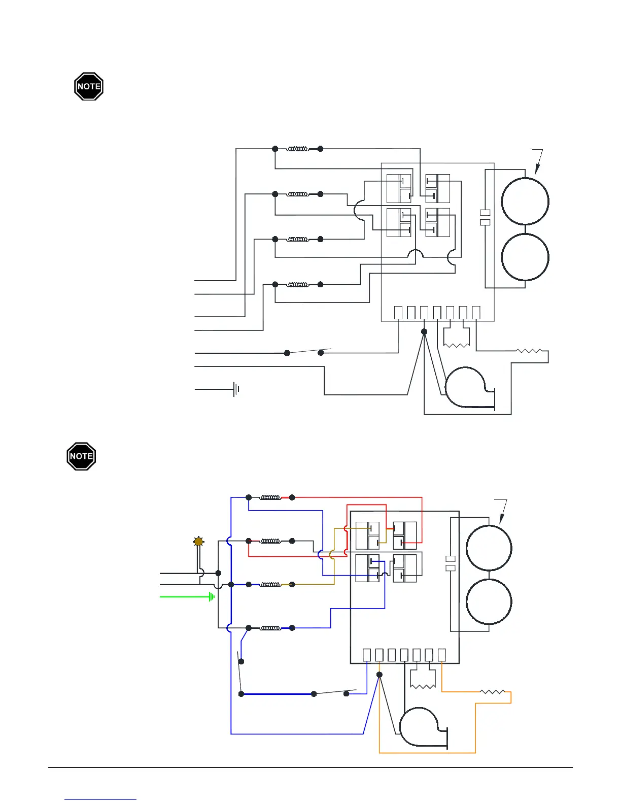
Connections shown are for systems with a 208/240V blower. If utilizing a 115V blower and
controls circuit, the blue/black (L1) connection must be the ungrounded (hot) conductor of the
power feed. Refer to the Unit Identication Label on the lower left side panel for proper blower
and heating element voltages.
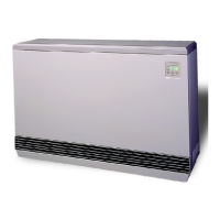
Model 2102 (plug-in heater)
Connections shown are for systems with a 115V blower. Refer to the Unit Identication Label on
the lower left side panel for proper blower and heating element voltages.
INTERNAL LINE VOLTAGE WIRING DIAGRAMS
Black
Yellow
Blue
Blue
Blower Circuit
Green
Red
Black
Black
Blue/Black
Black
Charge Circuit #2
Heater Controls and
Limit
Temperature
Output
Red
Charge Circuit #1
Element #1
Element #2
Red
Element #3
Blue
Yellow
Element #4
Blower
Orange
Relay #1
Relay #3
Limit
Base I/O PCB
Resistor
L1
Resistor120 240 Blower
Control
Resistor
Orange
Damper
Damper
Relay #4
Relay #2
Charging
Clearance
Violation
Limit
Red
If Equipped from Factory
SWITCH
Element #1
Element #2
Element #3
Element #4
Blue/Black
Blue
Power
Cord
Black
TIP
Green
White
Blower
Orange
Relay #1
Relay #3
Base I/O PCB
Resistor
Resistor
Output
Temperature
Limit
120
L1
Blower240
Damper
Control
Resistor
Orange
Damper
Blue
Yellow
Charging
Limit
If Equipped from Factory
Black
Relay #2
Relay #4
Clearance
Violation
Limit
Red
Power
Indicator
Light