EasyManua.ls Logo

Steffes 3100 Series - Internal System Wiring Diagram - Low Voltage

Default Icon
40 pages
Print Icon
To Next Page IconTo Next Page
To Previous Page IconTo Previous Page
Loading...
Appendix
Appendix n A.13 Comfort Plus
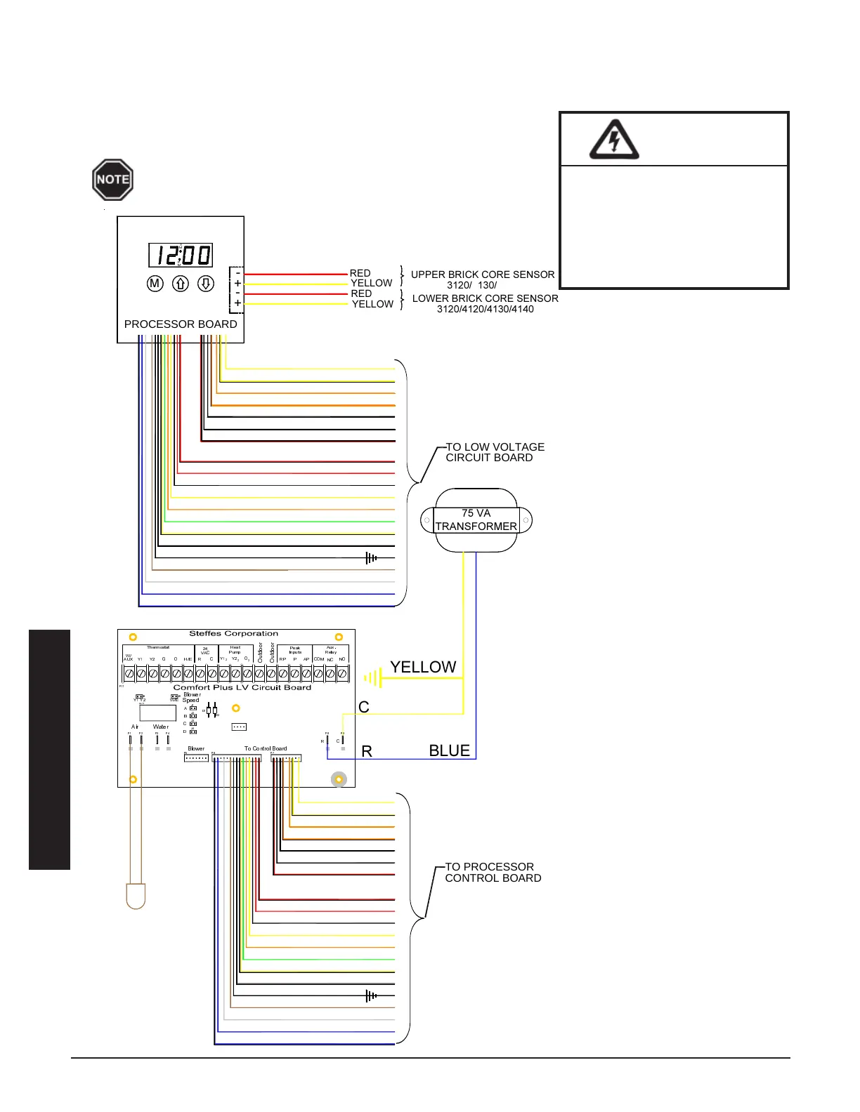
INTERNAL SYSTEM WIRING DIAGRAM - LOW VOLTAGE
The outdoor temperature sensor, room thermostat, and peak control device are connected via low voltage wiring.
System Low Voltage Wiring Diagram
The "R" and "C" positions in the low voltage terminal
strip may be used as a source of 24 VAC for powering
external low voltage devices (60 VA maximum).
HAZARDOUS VOLTAGE: Risk
of electric shock. Can cause
injury or death. All low volt-
age wiring must be segre-
gated from line voltage
circuits in the system.
WARNING




































 !
"#$%
&

'(




PROCESSOR BOARD
TO LOW VOLTAGE
TO PROCESSOR
CONTROL BOARD
CIRCUIT BOARD








"Y2"
2




!
!



!




!

!


"SC"
19
"RS"
20
"W"
10
"P"
"DS"
"OS"
"C"
"O"
"G"
"AP"
"Y"
15
17
18
16
13
14
11
12
"COM"
"RP"
"E"
"NO"
"NC"
"O2"
"R"
7
8
9
5
6
3
4

"R"
1

 !


1
17



!
19
20
18

9

!



!

13
15
16
14
11
12
10
!





!
5
7
8
6
3
4
2