4
INSSGH1213
INSTALLATION
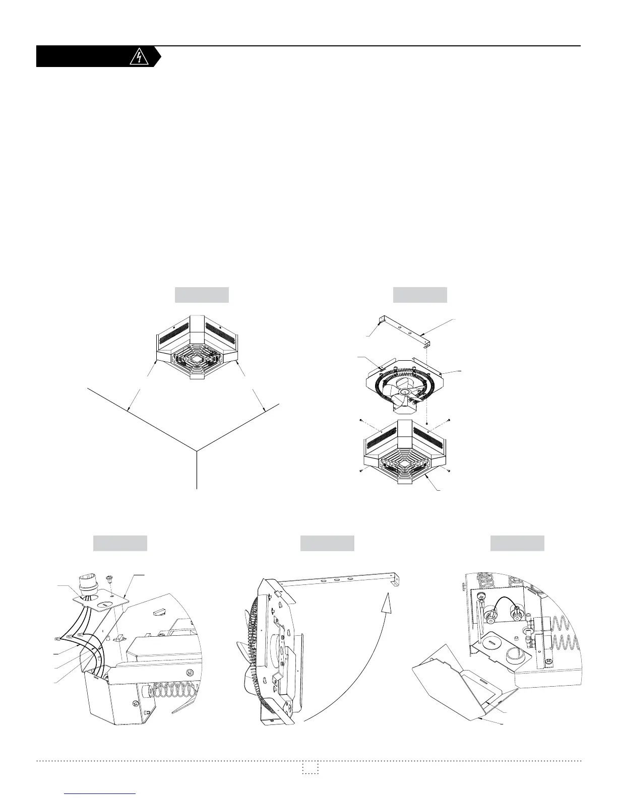
These units require a minimum mounting height of 8 feet (2.44 m) from
Also, keep at least 12 inches away from any vertical surfaces or walls
(see Fig.1).
1. Remove the external cover of the unit and set aside (4 screws, Fig. 2).
2. Remove the mounting bracket (1 screw and hook, Fig. 2)
3. Screw the mounting bracket to the ceiling and make sure the
ceiling structure is strong enough to support the unit. Make sure
the mounting bracket is installed in such a way that the unit will sit
straight and level. (Fig. 2)
4. Hook the slotted side of the internal assembly to the mounting
Make sure a wall mounted thermostat is installed to control the heater.
6. Provide a sufficient length of wire to facilitate the connections, which
are made while the unit is still hanging from the bracket. (Fig. 4)
7. Remove the back wiring compartment plate and knock down the 7/8
feed wire through it.
8. Make the electrical connections using the supplied wirenuts. Connect
the ground wire. Make sure all connections are secure and tight.
9. Replace the back wiring compartment plate. Swing the other half of
the internal assembly into position and screw the assembly to the
bracket with the screw(s) previously removed in step 2. (Fig. 4)
10. Replace the external cover and screw it into place with the four
screws removed in step 1.
11. Test the unit to make sure it is running properly.
12.
FIGURE 1
FIGURE3
FIGURE 2
FIGURE 4 FIGURE 5
12po MIN.
(305mm)
12po MIN.
(305mm)
SUSPENSION
HOOK
MOUNTING BRACKET
INTERNAL ASSEMBLY
SLOT
EXTERNAL
COVER
COMPARTMENT
PLATE
L2
RED
L1
KO.
7/8
BLACK
GREEN
WIRING DIAGRAM