INSSQBF0700607
5
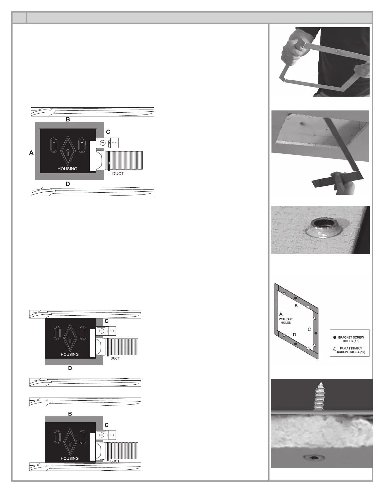
INSTALLATION OF THE MOUNTING BRACKET (continued)
Fan housing centered between the ceiling joists
• If there is no sufficient room to insert the bracket through the cut-out, then break off side A of
the bracket (break along the fold lines where side A borders side B and D). (Fig. 5.2 & 5.3)
• The mounting bracket installs within the ceiling, affixing to the top side of the ceiling. Place
the bracing with the tapered ends of the screw holes facing down (protruding ends facing
up). (Fig. 5.4)
• Secure the mounting bracket to the ceiling by screwing 3 screws through the corresponding
pencil marks on the bottom side of the finished ceiling (Fig. 5.5). Avoid countersinking the
screws below the surface of the finished ceiling. (Fig. 5.6)
Attic view – fan housing centered between the ceiling joist
OR
Fan housing located against one of the joists
• Always break-off side A of the mounting bracket (break along the fold lines where side A
borders side B and D) prior to inserting it through the ceiling cut-out (Fig. 5.1 and 5.2)
• The mounting bracket installs within the ceiling, affixing to the top side of the ceiling. Place the
bracket with the tapered ends of the screw holes facing down (protruding ends facing up).
(Fig. 5.4)
• Secure the mounting bracket to the ceiling by screwing 2 screws through the corresponding
pencil marks on the bottom side of the finished ceiling (Fig. 5.5). The screws will penetrate
the ceiling and then the bracket. Avoid countersinking the screws below the surface of the
finished ceiling. (Fig. 5.6)
Attic view – fan housing located against one of the joists.
Fig. 5.2
Fig. 5.3
Fig. 5.4
Fig. 5.5
Fig. 5.6
9