ELECTRONIC THERMOSTAT FOR
THE SMART HOME
STZW402+
THE THERMOSTAT MUST BE INSTALLED BY A CERTIFIED
ELECTRICIAN.
Connect the thermostat to a 120 to 240 VAC power source ONLY and
comply with load limits.
WARNING – HIGH VOLTAGE. Turn off the power supply before
installation and maintenance. Leave at least 12 in. (30 cm)
clearance around the thermostat to ensure that it is properly
vented.
SAVE THESE INSTRUCTIONS
1-844-STELPRO
WWW.STELPRO.COM
OWNER’S
MANUAL
IMPORTANT INSTRUCTIONS
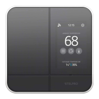
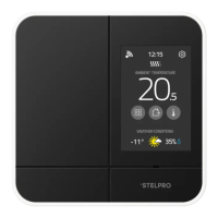
INTERFACE
FONCTIONS
BEFORE YOU GET STARTED
INSTALLATION
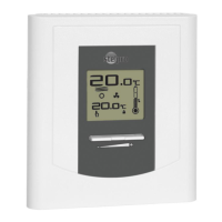
This thermostat is designed to control baseboard and convector. It
may be added (included) in a Z-Wave network.
THIS THERMOSTAT IS NOT COMPATIBLE WITH THE FOLLOWING INSTALLA-
TIONS
• Inductive load
• Central heating system
• Fan heater (unit consisting of a motor and a fan)
• Heating load outside the specied ratings (refer to the Technical
Specications section)
PARTS SUPPLIED
• one (1) thermostat
• one (1) wall mounting plate located at the back of the thermostat
• two (2) mounting screws
• two (2) solderless connectors suitable for copper wires
The thermostat must be mounted to a connection box on a wall fac-
ing the heating unit, at around 1.5 m (5 feet) above the oor level, on
a section of the wall exempt from pipes or air ducts.
Do not install the thermostat in a location where temperature mea-
surements could be altered. For example:
• close to a window, on an external wall, or close to a door leading
outside
• exposed directly to the light or heat of the sun, a lamp, a replace
or any other heat source
• close to or in front of an air outlet
• close to concealed ducts or a chimney
• in a location with poor air ow (e.g. behind a door) or with frequent
air drafts (e.g. head of stairs)
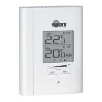
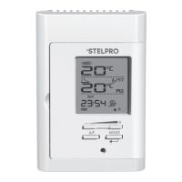
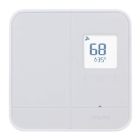
AMBIENT TEMPERATURE
The temperature is displayed either in °C with a 0.5 °C resolution
or in °F with a 1 °F resolution. The screen will display LO if the tem-
perature drops below 0 °C (32 °F) and will display HI if the tempera-
ture rises above 50 °C (122 °F).
TEMPERATURE SETPOINTS
The setpoint may be edited by the user using the UP and DOWN
buttons located on the thermostat. The setpoint may also be modi-
ed through the Z-Wave network.
The minimum setpoint is 5 °C (41 °F) and the maximum setpoint is
30 °C (86 °F).
NOTE: if the setpoint is set at 7 °C (45 °F) or below, the frost warning
icon will be displayed to warn the user that water pipes might be
subject to freezing.
HEATING POWER INDICATOR
Whenever the thermostat is actively heating the room, the heating
status graph will display the heating percentage.
0 bar : 0 %
1 bar : 1-25 %
2 bars : 26-50 %
3 bars : 51-75 %
4 bars : 76-100 %
THERMOSTAT MODE
The thermostat has three modes: Comfort, Eco and Off. The rst
two modes have their own preestablished setpoint. Comfort: 21 °C
(70 °F), Eco ( ): 17 °C (63 °F).
The user may change the setpoint to any value in the range de-
scribed in the setpoint section.
When the Eco mode is active, the Eco icon ( ) is displayed on
the LCD.
The thermostat mode may be changed locally on the thermostat by
pressing the UP and DOWN buttons simultaneously for less than 3
seconds while on the main screen. The Eco setpoint is local to the
thermostat and cannot be edited through the Z-Wave network.
Z-WAVE CONNECTIVITY ( )
If the thermostat is added (included) to a Z-Wave network, the
connectivity icon will be displayed on the LCD, if the device is
removed (excluded) from a Z-Wave network, the connectivity icon
will disappear. The connectivity icon may blink if there is an issue
with the Z-Wave radio circuit.
ADVANCED SETTINGS ( )
There are 6 advanced settings menus on the thermostat.
The advanced settings are the following:
1. Z-Wave menu : used to add (include) or remove (exclude) the
thermostat from a Z-Wave network
2. Display format: used to switch the temperature format between °C
and °F
3. Lock mode : used to lock the thermostat to prevent unautho-
rized tampering.
4. Outdoor temperature display : used to switch the outdoor
temperature display on or off (when available). When set to (On),
the outdoor temperature will be displayed if it’s available. When
set to (Off), the outdoor temperature will not be displayed and the
setpoint will always be displayed.
5. Backlight status while idle: used to set the backlight intensity
when the thermostat is idle.
0%: the backlight will turn off after 15 seconds of inactivity
50%: the backlight will dim to 50% after 15 seconds of inactivity
100%: the backlight will always be at full intensity
6. °STELPRO information menu: used to gain information on the
product
• Version
• Date of production (mm/dd)
• Year of production
• Z-Wave Node Id
• Baseboard/convector control checksum
• Reset to default
MODIFICATION OF THE SETTINGS:
• To gain access to the advanced settings root menu, press the UP
and DOWN buttons simultaneously for 3 seconds.
• At this point each setting (1 to 6) may be accessed by using the
UP and DOWN buttons.
• To edit a value, choose a setting then simultaneously press the UP
and DOWN buttons once. Press the UP or DOWN button to edit
the value.
• Conrm your choice by pressing the UP and DOWN buttons simul-
taneously one time at which point the icon will momentarily ash
rapidly if a change has been made.
• To exit the advanced settings press the UP and DOWN buttons
simultaneously for 3 seconds at any time. If the thermostat is left
idle it will revert back to the main screen after 30 seconds
1
ATTACH THE MOUNTING PLATE
2
CONNECT THE POWER
SUPPLY WIRES
3
ATTACH THE THERMOSTAT
1. Cut off power supply on lead wires at the electrical panel
in order to avoid any risk of electric shock.
2. If an existing thermostat is being replaced, remove the previ-
ous thermostat.
3. Ensure that the air vents of the Ki thermostat are clean and
clear of any obstruction.
4. Using a screwdriver, loosen the screw retaining the mounting
base of the thermostat (do not completely remove the screw).
Then, remove the mounting base at the back of the thermostat
by tilting it downward, then towards you.
5. Align and secure the mounting base to the connection box
using the two screws supplied.
1. Pass the wires from the wall through the hole at the base of the
mounting base and connect them using the solderless con-
nectors supplied. When making the connection with aluminum
wire, make sure that you are using connectors identied CO/
ALR. Please note that the thermostat wires do not have polari-
ty. Therefore, the way they are connected is not important.
2. Place all the wires into the connection box.
1. Align the little slots located on the top of the thermostat with
those on the mounting base and secure the thermostat to the
mounting base. Note that you can also position the thermostat
on the left or the right side of the junction box (see below).
Then tighten the screw at the bottom of the unit.
2. Turn the power on.
2-WIRE INSTALLATION 4-WIRE INSTALLATION
Ambient temperature
Heating status
Thermostat mode
Advanced settings
Set point temperature OR
outdoor temperature
(requires external
sensor over Z-Wave)
Lock mode
Frost warning
Z-Wave connectivity
Z-WAVE INCLUSION/EXCLUSION ( )
INCLUSION:
Make sure the Z-Wave hub is in the include mode (refer to your
Z-Wave hub instruction manual).
To add (include) the thermostat to a Z-Wave network, enter Menu
1 (Z-Wave menu) and select (On). Then press the UP and DOWN
buttons to start the inclusion process. During inclusion, (On) will be
blinking and the connectivity icon will be animated in an increas-
ing pattern. When the inclusion process has been completed, (On)
will be displayed solid. If an error occurs, (Err) will be displayed for 3
seconds then the screen will revert to (Off) selection.
EXCLUSION:
Make sure the Z-Wave hub is in the exclude mode (refer to your
Z-Wave hub instruction manual).
To remove (exclude) the thermostat from a Z-Wave network, enter
Menu1 (Z-Wave menu) and select (Off). Then press the UP and
DOWN buttons to start the exclusion process. During exclusion,
(Off) will be blinking and the connectivity icon will be animated
in an decreasing pattern. When the exclusion process is complete,
(Off) will be displayed solid. If an error occurs, (Err) will be displayed
for 3 seconds then the screen will revert to (On) selection.
To achieve better network performance, it is recommended to
always add (include) your Z-Wave devices starting from the closest
one to the farthest one.
FACTORY RESET
The thermostat may be manually reset to its original factory set-
tings.
When this is performed, all parameters are reset to their default
values and the thermostat is removed (excluded) from the Z-Wave
network.
To reset the thermostat to its default settings:
1. Enter the advanced settings
2. Enter the °STELPRO menu (menu 6)
3. Navigate to the (def) screen using the UP or DOWN buttons.
4. Enter the (def) menu by pressing the UP and DOWN buttons for
less than 3 seconds
5. Select (yes) and conrm the selection by pressing the UP and
DOWN buttons for less than 3 seconds.
If the thermostat was added (included) in a Z-Wave network, it will
send a (device reset locally) notication.
The thermostat will then reset itself.
Please use this procedure only when the network primary controller
is missing or otherwise inoperable.
POWER OUTAGE
If a power outage occurs, the thermostat will stop working but all
conguration is saved.
OUTDOOR TEMPERATURE ( )
When connected to a Z-Wave network, the thermostat may display
the outdoor temperature provided by an external sensor.
When available, the outdoor temperature is displayed instead of the
setpoint, providing that the outdoor temperature display setting is
set to (On).
If no temperature is received within a 4-hour timeframe, the outdoor
temperature will disappear and the setpoint will be displayed.
In order to display the outdoor temperature, an external sensor
needs to be part of the Z-Wave network. It may be a physical sen-
sor or a weather station app.
Refer to your Z-Wave hub controller instructions manual to nd how
to associate both devices. On some Z-Wave hub controllers, an
app may be used to provide the outdoor temperature.