PUMP TUBE REPLACEMENT
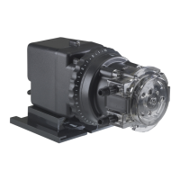
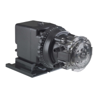
Classic Series Single Head Adjustable & Fixed Output Pumps
II REMOVE OLD TUBE
➊
Remove and set aside cover and screws.
➋ S
et feed rate dial on setting L.
➌ Turn pump on and let it run until one of three
roller assembly slots lines up with the tube
fitting on the suction side. Figure A
➍ Turn pump off.
➎ L
ift tube fitting out of housing slot and pull it
toward center of roller assembly. Figure B
➏ Turn pump on and allow roller assembly to jog
while guiding tube, with tension, up and out of
h
ousing. Figure C
➐ Turn pump off. Remove and discard pump tube.
➑ R
emove roller assembly, shaft, and housing.
➒ Use non-citrus all-purpose cleaner to clean
chemical residue from pump head housing,
roller assembly and cover.
➓ Check housing for cracks. Replace if cracked.
⓫Ensure rollers turn freely. Figure D Replace
roller assembly if the rollers are seized or worn
o
r if there is a reduction or lack of output from
the pump.
⓬R
einstall clean tube housing.
⓭Install shaft into feed rate control, apply
A
quaShield
™
t
o the shaft tip.
⓮Install roller assembly.
III INSTALL NEW TUBE
I
MPORTANT! DO NOT lubricate pump tube or
roller assembly.
➊ Manually rotate the roller assembly
counterclockwise to align one of three roller
assembly slots with the suction side housing slot.
➋ Place tube fitting into suction side slot of the
housing and the roller assembly slot. Figure E
➌ W
ith pump setting on L, hold tube fitting and
jog roller assembly by turning pump on.
I
MPORTANT! Avoid rotating wrist, which can result in
a twisted tube that will not center. DO NOT force tube
and be careful of your fingers.
➍ Guide tube with slight tension toward the
center to prevent pinching between housing
and roller assembly. If the tube is pinched
during installation, discard. Figure F
➎ When tube reaches the discharge tube housing
slot, turn pump off.
➏ Turn dial ring to setting 10, hold tube fitting
firmly, do not pull, and turn pump on.
NOTE: A used tube will have stretched
approximately 3/4" and the new tube will
appear to be stiff and short. Follow directions
to allow rollers to stretch tube into place.
➐ Allow rollers to stretch tube into place while
guiding tube into slot. Figure G
➑ Turn pump off.
➒ Apply a small amount of AquaShield
™
to cover
bushing ONLY and replace cover and two
screws. Figure H Leave the front screw between
the tube fittings loose for centering the tube in
the next step.
IV CENTER NEW TUBE
➊
To center pump tube on rollers, set feed rate dial to setting 10. Turn pump on.
➋ Turn the tube fitting on the suction side not more than 1/8 of a turn in the
direction tube must move. Figure I
➌ DO NOT let go of fitting until tube rides approximately in center of rollers.
➍ Turn pump off, let go of fitting, and finger tighten cover screws.
➎ Inspect the suction and discharge lines, point of injection, and check valve
duckbill for blockages. Clean all deposits and/or replace parts as required.
Failure to do so may lead to poor pump performance, including shortened
tube life. Reference your pump owner's manual for details.
➏ Reconnect the suction and discharge lines.
NOTE: Cover screws are self-tapping and must be backed in to locate original thread
before securing. If a screw boss is stripped, use alternate bosses and position
opposite from each other. Never secure the cover plate with more than 2 screws.
TUBE CHANGE FOR FIXED OUTPUT PUMP
To install a new tube in a fixed output pump, follow the
instructions and utilize the on/off switch to jog the
roller assembly in the absence of the feed rate control.
I PREPARATION
➊
Follow all safety precautions prior to tube replacement.
➋ Prior to service, pump water or a compatible buffer solution through the pump
and suction and discharge lines to remove chemical and avoid contact.
➌ Turn pump off.
➍ Disconnect the suction and discharge connections from pump head.
➎ Plug power cord into constantly energized, properly grounded receptacle for
tube replacement.
Pump Manufactured Before April 29, 2011 Pump with QuickPro
®
Pump Head Manufactured After April 29, 2011
I P
RE
P
A
RAT
I
O
N
➊ Follow all safety precautions prior to tube replacement.
➋ Prior to service, pump water or a compatible buffer solution through the pump and suction and discharge lines to remove chemical and avoid contact.
I
I REMOVE THE PUMP TUBE
➊ Turn the pump off and unplug the power cord. On the adjustable model, ensure that the feed rate control is set to 10. Figure A
➋ Depressurize and disconnect the suction and discharge lines.
➌ O
pen the back and front of the latches on both sides of the head. Carefully fold latches back to prevent contact with the
cover. Figure B
For CE pump only: Remove the safety screw on cover.
➍ Remove the tube housing cover and flip to use as a tool in the next step. Figure C
➎ Align the center of the inverted cover with the center of the roller assembly so that the three holes on the face of the
c
over align with the three knurled lugs on the roller assembly. Position the cover feet near the tube fittings. Figure D
NOTE: The roller assembly needs to be collapsed to remove the tube.
➏ On the adjustable pump, hold the feed rate control securely. On the fixed output pump hold the pump securely. Use the
tube housing cover as a wrench and quickly (snap) rotate the cover counter-clockwise to collapse the roller assembly.
T
he tube will no longer be pressed against the tube housing wall. Figure E
NOTE: Counter-clockwise is viewed from facing the head of the pump.
➐ Remove and discard the pump tube. Figure F
➑ Remove the roller assembly, and the tube housing. On the adjustable pump also remove the shaft. Set them aside to
reinstall later.
➒ Use a non-citrus all-purpose cleaner to clean chemical residue from the tube housing, roller assembly and cover.
➓ Check the housing, cover and roller assembly for cracks and replace if cracked.
⓫Ensure the rollers turn freely. Replace the roller assembly if the rollers are seized or worn or if there is a reduction or lack of
output from the pump. Figure G
⓬R
einstall the clean tube housing. On an adjustable pump, also install the shaft into the feed rate control.
⓭Apply AquaShield
™
to the shaft tip.
⓮Install the roller assembly.
I
II INSTALL THE PUMP TUBE AND EXPAND THE ROLLER ASSEMBLY
I
MPORTANT! DO NOT lubricate pump tube or roller assembly.
➊ Ensure the power to the pump is off and the power cord is unplugged. On the adjustable model, ensure that the feed rate control
is set to 10. Figure H
➋ Place the new tube in the pump head; use your fingers to center it over the rollers. Figure I
➌ Place the tube housing cover on the tube housing, affix the front latches to the cover lip and then press the latches back to
secure. Be sure the cover is seated with the sleeve bearing on the shaft and is flush with the housing before latching. Figure J
➍ With the cover latched, plug the pump in and turn the power on. Allow the pump to run the roller assembly in its collapsed
position for approximately two minutes to relax the tube. Figure K
➎ Turn the pump off and unplug the power cord.
➏ Remove the tube housing cover and flip to use as a tool in the next step. Figure L
➐ Align the center of the inverted cover with the center of the roller assembly so that the three holes on the face of the cover
align with the three knurled lugs on the roller assembly. Position the cover feet near the bottom. Figure M
NOTE: The roller assembly needs to be expanded so the tube is pressed against the tube housing wall.
➑ E
xpand roller assembly.
CAUTION: Use care when expanding roller assembly, excessive force can crack the hub and lead to failure of the roller assembly.
➒ Apply a small amount of AquaShield
™
to the cover bushing ONLY. DO NOT lubricate the pump tube. Figure P
➓ Place the tube housing cover (feet first) on the tube housing, affix the front of the latches to the cover lip and then press the
latches back to secure. Be sure the cover is seated with the sleeve bearing on the shaft and is flush with the housing before
latching. Figure Q
F
ixed Output Model
(manufactured before
04/29/11)
Only the Stenner fan
brake tool should be used for this step.
a. Insert the fan brake tool into the
vent in the rear of the motor housing.
Refer to the figures below.
NOTE: The fixed output pump
doesn’t have a clutch so the fan
brake keeps the shaft from rotating
when expanding the roller assembly.
b. Holding the pump securely, use the
cover as a wrench and quickly (snap)
rotate the roller assembly clockwise
to expand the roller assembly. The
tube will be pressed against the
tube housing wall. Figure N & O
NOTE: Clockwise is viewed from
facing the head of the pump.
c. Remove the fan brake tool. Proceed
to step 9.
Fixed Output Model
(motor vent with key slot,
manufactured after 04/29/11)
a. Slide one latch out to remove it
from the tube housing. Insert the
latch end into the key slot in the
vent in the rear of the motor
housing. While pressing the latch
into the rear of the motor, gently
rotate the cover clockwise until it
stops. Refer to the figures below.
b. Holding the pump securely, use the
cover as a wrench and quickly
(snap) rotate the roller assembly
clockwise to expand the roller
assembly. The tube will be pressed
against the tube housing wall.
Figure N & O
NOTE: Clockwise is viewed from facing
the head of the pump.
c. Remove the latch from the vent and
re-attach it to the tube housing.
Proceed to step 9.
IV CENTER NEW TUBE
➊ Ensure the pump is off. Lift the latch located between the tube fittings, leaving the end of the latch engaged with the lip on the
tube housing cover. Leave the latch on the opposite side engaged. Figure R
➋ Plug the pump in and turn it on. Turn the tube fitting on the suction side not more than 1/8 of a turn in the direction tube must
move. Figure S
➌ DO NOT let go of fitting until tube rides approximately in center of rollers.
➍ Turn the pump off, let go of the fitting, and secure the latch between the fittings. Figure T
For CE pump only: Reinstall the safety screw on the cover.
➎ Inspect the suction and discharge lines, point of injection, and check valve duckbill for blockages. Clean all deposits and/or
replace parts as required. Failure to do so may lead to poor pump performance, including shortened tube life. Reference your
pump owner's manual for details.
➏ Reconnect the suction and discharge lines. DO NOT allow tube fittings to turn inside the pump housing.
➐ Turn the pump on and run for one minute to verify operation.
INSPTR 020519
TO BE INSTALLED AND MAINTAINED BY PROPERLY TRAINED PROFESSIONAL INSTALLER ONLY. READ MANUAL & LABELS FOR ALL SAFETY INFORMATION & INSTRUCTIONS.
A
B
C
D
E
F
G
H
I
A
B
C
D
E
F
G
H
I
J
K
L
M
N
O
P
Q
R
S
T
Jacksonville, Florida USA www.stenner.com © Stenner Pump Company All Rights Reserved
This information is not intended for specific application purposes. Stenner Pump Company reserves the right to make changes to prices, products, and specifications at any time without prior notice.
W
ARNING
Adjustable Model
• Hold the feed rate control
securely, use the cover as a
wrench and quickly (snap)
rotate the roller assembly
clockwise to expand the roller
assembly. The tube will be
pressed against the tube
housing wall. Figure N & O
Proceed to step 9.
NOTE: Clockwise is viewed from
facing the head of the pump.
WARNING
S T E N N E R P U M P C O M P A N Y