10
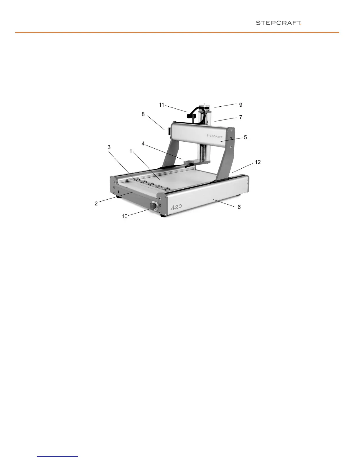
4 = 43.0 mm / 1.69 inch tool seat e.g. for milling spindle, hot cutter, engraving point
5 = X-axis guiding for driving and axis guiding
6 = Y-axis guiding for driving and axis guiding, incl. inspection flap for cleaning and maintenance
7 = Z-axis guiding for driving and axis guiding
8 = Step motor X-axis to move the slide of the X-axis
9 = Step motor Z-axis to move the slide of the Z-axis
10= Emergency-Stop switch to stop the machine quickly (only in emergency situations)
11 = Cable collector to cover X- and Z-motor/limit switch cable
12 = Backside of the machine with connector block for power supply and computer
4 COMMISSIONING
4.1 INSTALLING THE MACHINE
The machine must be positioned on an absolutely level even working table so that it stands safely and can neither
slip nor tilt over.
All mobile parts of the machine must have sufficient space in order that they can be moved without collisions.
The cable duct of the system-guided tool e.g. the milling spindle must be designed in a way that the spindle cable
is not being clamped between the guide ways of the machine.
It is necessary to well attain and operate the machine.
CAUTION: It is in particular necessary to reach the Emergency-Stop switch at any time; it must not be obstructed.
Provide for sufficient illumination of the machine site and the working place surrounding the machine.
Place the PC which controls the machine nearby the machine so that you can have an eye on both.
4.2 ENVIRONMENTAL CONDITIONS
Install the machine in a closed room.
Keep the environmental temperature of the machine dust-free. Too high dust loading can cause damages on the
system.
The humidity should be within normal limits for humidity content inside. Protect the machine against wetness and
humidity.
The perfect environmental temperature for the system is from 18°C to 25°C, from 64°F to 77°F respectively.