31
TROUBLE SHOOTING Diesel Burner Component Test
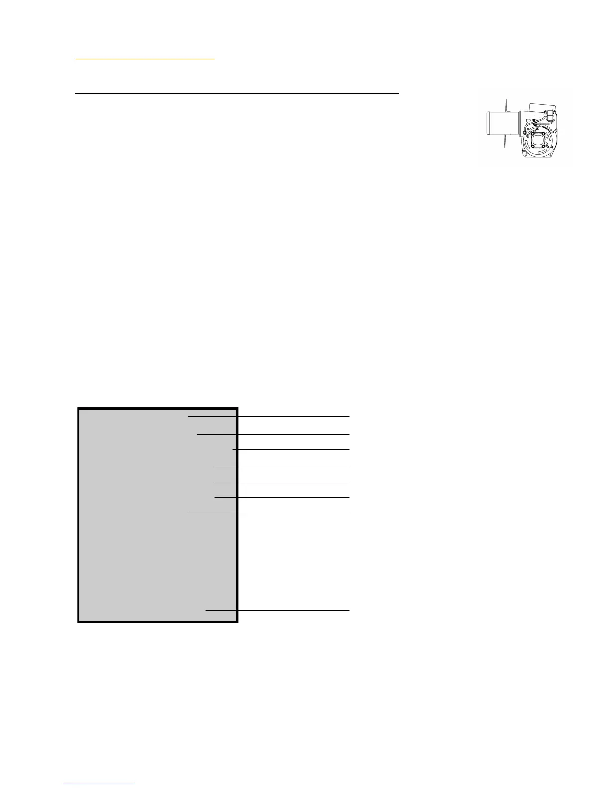
PRIMARY CONTROLLER
A10008216
RED To Main power Switch
WHITE To Thermostat
WHITE/RED Not Used
YELLOW To Photo Electric Eye
YELLOW To Photo Electric Eye
ORANGE To Fuel Valve and Blower Motor
BLUE To Igniter Transformer
BLACK To Ground
Primary Controller Burner MTD/Hard Wired
NOTE: The primary controller can be bench tested for proper operation us-
ing an automotive type, 12 volt battery as a power source. Refer to the wir-
ing schematics for wire identification.
1. Remove controller from burner. Mark all wires for proper reassembly.
2. Using two test lights, or volt meters, connect one to the blue wire, and one to the white/
orange wire of the controller. Connect the black leads of your test instruments to the nega-
tive (-) terminal of the battery.
3. Connect the black wire from the controller to the negative (-) terminal of the battery.
4. Connect the red, white/red, and the white wires together, then connect these three wires
to battery (+) terminal. Both test instruments should show voltage for approximately 15
seconds. After 15 seconds, the controller should "lock out" and no voltage will be present.
5. Repeat step #4, only this time connect the two yellow wires from the controller together
three seconds after applying power to the three wires of the controller. (This simulates the
controller receiving a "flame" signal from the photo electric eye). The white/orange wire
should show voltage as long as the controller is hooked to the battery. The blue wire
should only show voltage for about 15 seconds. Replace the controller if it fails any of
these tests.