35
Fenwal Ignition Control
The Ignition Controller can be tested for proper operation using an automotive type 12 volt
battery as a power source. A propane torch, and a 12 volt test light will also be needed. Do
not use a digital volt/ohm meter, as it may give false readings for these tests.
1. Disconnect wires as necessary to perform these tests. Mark all wires for proper reassem-
bly.
2. Connect one lead of your test light to the brown wire from the fuel valve. Connect the oth-
er lead to neg. ( - ) terminal of battery.
3. Be sure the yellow wire from the controller is connected to ground. (neg. terminal of bat-
tery).
4. While observing your test light, apply power to the red wire on the controller by
turning on the main power switch and thermostat (if equipped). The test light
should light up and sparks will be present at the electrodes for approximately six
seconds, then the controller should "lock out." The sparks will stop and the test light will
go out.
5. Repeat step #4, only this time direct flame from a propane torch across the sensing and
ground electrodes two seconds after applying power to the controller.
6. The sparks should stop and the brown wire (fuel valve) should show voltage as long as
the flame is directed across the electrodes.
7. Remove the flame and the sparks should reappear for six seconds; this is the trial for re-
ignition. If the flame is not re-established, the system "locks out".
8. Be certain all wiring is correct and undamaged, then replace the controller if it fails any of
these tests.
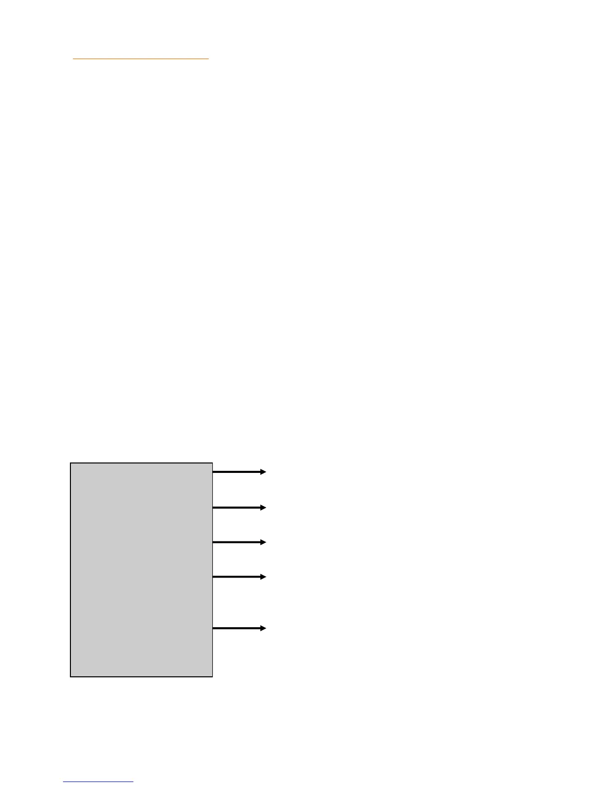
HIGH VOLTAGE
YELLOW
BLACK
BROWN
RED
To electrodes
To ground
To flame sensing electrode
To fuel valve
To power
FENWAL
TROUBLE SHOOTING Fenwal Ignition Tests