This document provides a quick start guide for the Stepperonline T6 AC Servo system, covering its connection, basic operation, and tuning procedures.
Function Description
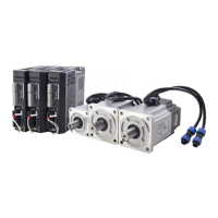
The Stepperonline T6 AC Servo system is designed for precise position control, utilizing a pulse and direction (Pul + Dir) input method. It comprises a T6 drive, a motor, and various cables for power, encoder feedback, and tuning. The system supports JOG trail operation for initial testing and position control for more advanced applications. The drive features real-time auto-gain tuning and various control modes to optimize performance for different applications.
Important Technical Specifications
Control Modes:
- Pr0.01 (Control mode):
0: Position Mode (default for this guide).1: Velocity Mode.2: Torque Mode.6: Pr-Mode (combination mode, allowing selection between 1st and 2nd modes via C-MODE input).
Real-time Auto-gain Tuning (Pr0.02):
0: Manual mode (auto-gain tuning disabled).1: Standard mode (recommended for interpolation movement; Pr1.00-1.14 values are linked to Pr0.03).2: Positioning mode (recommended for point-to-point movement; Pr1.00-1.14 values are linked to Pr0.03).
Gain Adjustment (Pr0.03 - Machine rigid):
- Range: 50-81.
- Default: 70.
- Function: Selects machine stiffness for real-time auto-gain tuning. Lower values increase velocity response and servo stiffness, but may lead to oscillation or vibration. Changes are applied when the motor is stopped.
Inertia Ratio (Pr0.04):
- Range: 0-10000.
- Default: 250.
- Function: Represents (load inertia/rotate inertia) × 100%. Crucial for optimal performance.
Pulse Polarity Setting (Pr0.06):
- Range: 0/1.
- Function: Changes the rotation direction.
Pulse Input Model (Pr0.07):
- Range: 0/1/2/3.
- Function: Sets the command pulse input mode according to the controller signal.
Command Pulse Per Motor Rotation (Pr0.08):
- Range: 0-8388608.
- Default: 10000 pulses per revolution.
- Function: Defines the electronic gear ratio. If set to 0, Pr0.09 and Pr0.10 become valid for setting the electronic gear ratio.
Electronic Gear Ratio (Pr0.09 - Numerator, Pr0.10 - Denominator):
- Range: 0-8388608.
- Function: Used to set non-integral electronic gear ratios when Pr0.08 is 0.
Input Pulse Frequency:
- The drive cannot identify input pulse frequencies higher than 500K.
- With 10000 ppr, a command bandwidth of 3000rpm can reach 500k. For motor speeds above 3000 rpm, the pulse per revolution must be lower than 10000.
I/O Signal Specifications:
- Digital Input (COM+): Two-way digital input with common terminal, configurable for 12VDC-24VDC.
- Digital Output (SO1, SO2, SO3): Open-collector outputs. Maximum voltage 25V, maximum current 50mA. If the load is inductive, an anti-parallel freewheeling diode must be connected.
- Pulse Input: Supports single-ended 24V pulse signal and differential 5V pulse signal. Hardware filtering provides a maximum bandwidth of 750kHz.
Position Command Smoothing Filter (Pr2.22):
- Range: 0-32767.
- Unit: 0.1ms.
- Default: 0.
- Function: Sets the time constant of the 1st delay filter for position command smoothing.
Position Command FIR Filter (Pr2.23):
- Range: 0-10000.
- Unit: 0.1ms.
- Default: 0.
- Function: Sets the time constant of the 1st delay filter for position command.
Mode Loop Gain (Pr0.00):
- Range: 0-32767.
- Unit: 0.1Hz.
- Default: 0.
- Function: Sets the bandwidth of MFC.
0: Disable the function.1: Enable the function, set bandwidth automatically (recommended for most applications).2-10: Forbidden and reserved.11-20000: Set the bandwidth manually, 1.1Hz – 2000Hz.
Usage Features
1. Connection:
- Cables: Connect the CN4 (Tune Cable), CN3 (Encoder Feedback Cable), L1/L2 (Drive Power Cable), U/V/W (Motor Power Cable), and PE (Ground Cable).
- Driver Installation: If necessary, install the driver for the tune software (Motion Studio) by navigating to "Device Manager" -> "Ports (COM&LPT)" -> "STEPPERONLINE Driver" -> "Update driver" and browsing for the driver in the STEPPERONLINE application folder.
2. JOG Trail (Initial Testing):
- Software Connection: Open Motion Studio, click "Com Connect," select the correct communication port and baud rate, then click "Connect."
- Run Testing:
- Set Pr0.03 (Stiffness) and Pr0.04 (Inertia ratio) parameters.
- Click "Servo Enable."
- Click "CCW" to run the motor counter-clockwise, then "Position 1" to save the limit.
- Click "CW" to run the motor clockwise, then "Position 2" to save the limit.
- Click "Run" to start the testing process.
- Monitor performance using the wave show during testing.
- Wave Show: Use the "Wave Show" function to capture and display real-time waveforms for position error, position setting, current feedback, and velocity feedback.
3. Position Control (Pul + Dir):
- Wiring: Refer to the provided wiring diagrams for single-ended 24V pulse signals and differential 5V pulse signals. Ensure correct connections for input/output signals and encoder feedback.
- Tuning Steps:
- Verify motor connection and recognition by the drive.
- Perform "run testing" to check motor operation.
- Set Pr0.02 (Real-time auto configuration) to
2 for positioning mode (or 1 for standard mode, 0 for manual mode).
- Choose the correct control mode (Pr0.01).
- Set Pr0.04 (Inertia ratio).
- Connect motor with load and tune stiffness (Pr0.03).
- Tune Pr2.22 and Pr2.23 for smoother movement.
- Set Pr0.06, Pr0.07, Pr0.08, Pr0.09, Pr0.10.
- Tune Pr0.00 for more stiffness if needed.
4. Simple Debugging for Position Control:
- Steps:
- Confirm pulse polarity (Pr0.06) and command input mode (Pr0.07).
- Modify Pr0.08 (command pulse per motor rotation) to set the electronic gear ratio. If using a non-integral ratio, set Pr0.08 to 0 and use Pr0.09 and Pr0.10.
- Set suitable inertia with Pr0.04 (suggest increasing/decreasing in multiples of 100).
- Adjust Pr0.03 (Machine rigid) to a suitable stiffness value, starting from a high value and decreasing until a sharp noise appears.
- After each parameter modification, save the changes and restart the power.
- Final Setting: Set Pr0.03=62 for basic position mode setting.
5. Tuning Dynamic Tracking Performance (Pr0.00):
- Pr0.02=2 (positioning mode): No need to tune dynamic tracking performance.
- Pr0.02=1 (interpolation movement): Very useful for tuning dynamic tracking performance. MFC function is useful for better dynamic tracking control and contouring cutting.
- Steps to use Pr0.00:
- Choose the right control mode (Pr0.01 = 0).
- Set Pr0.02=1 for interpolation movement.
- Set the inertia ratio (Pr0.04).
- Set up the rigidity (Pr0.03).
- Set up Pr0.00.
- For multi-axis synchronous movement, set Pr0.00 as 1 or more than 10.
- If no multi-axis synchronous movement is needed, set Pr0.00 as the same for all axes.
- If Pr0.00 is more than 10, start with 100, or 150, 200, 250, etc.
- Caution:
- Set up the right control mode, the correct inertia, and rigidity first.
- Do not change Pr0.00 when the motor is running, otherwise vibration occurs.
- Start with a small value for Pr0.00 and gradually increase it. A smaller value means smoother movement, while a bigger one means faster positioning.
Maintenance Features
- Parameter Saving: Always save parameters after modification and restart the power to ensure changes are applied.
- Driver Updates: Regularly check for and update the tune software driver if necessary to maintain compatibility and performance.
- Troubleshooting: The guide provides visual aids (waveforms) to monitor system performance and identify issues like position error, oscillation, or vibration during tuning.
- Error Prevention: The guide emphasizes stopping the motor before changing stiffness settings (Pr0.03) to prevent abnormal sound or oscillation. It also warns against changing Pr0.00 while the motor is running.
- Wiring Integrity: Use twisted wire with shielding for encoder signals and pulse inputs to minimize noise interference. Ensure proper polarity for power connections to prevent damage.