EasyManua.ls Logo

StepperOnline Y Series - User Manual

StepperOnline Y Series
6 pages
Print Icon
To Next Page IconTo Next Page
Loading...
2
User Manual for
Full Digital Stepper Driver
YSeriesOpenloop
Stepper Driver
Version 1.0
STEPPERONLINE®
©2019 All Rights Reserved
Attention: Please read this manual carefully before using the driver.
1 Introductions & Features
The Y series Open‐loop drivers are divided according to the driving power, which are DM420Y, DM542Y,
DM556Y, DM860Y. The Y series open loop drivers are digital stepper drivers with simple design and
easy setup. By implementing the advanced stepper control technology, this stepper drive is able to
power 2‐phase and 4 phase stepper motors smoothly with optimal torque and low motor heating &
noise. All the micro step and output current are done via DIP switches. Therefore, the Y series open
loop drivers are ideal choices for applications requiring simple step & direction control of NEMA 8, 11,
14, 16, 17, 23, 24 and 34 stepper motors. And features are showing below:
Anti‐Resonance for optimal torque, extra smooth motion, low motor heating and noise
Motor auto‐identification and parameter auto‐configuration for optimal torque from wide‐range
motors
Step & direction (PUL/DIR) control
Multi‐Stepping for smooth motor movement
TTL compatible and optically isolated inputs
Input voltage DC18~36V, DC20~50V, DC36~110V(AC18~80V)
Micro‐step resolutions: 200~6400, 200~40000, 400~40000
Output current settings: 0.3~2.2A, 1~4.2A, 1.7~5.6A, 2.4~7.2A
Soft‐start with no “jump” when powered on
Automatic idle‐current reduction
Protections for over‐voltage and over‐current
2 Specifications
2.1 Operating Environment and other Specifications (Tj = 25°C/77°F)
Cooling Natural Cooling or Forced Cooling
Operating
Environment
Environment Avoid dust, oil fog and corrosive gases
Ambient Temperature 0°C ~ 65°C (32°F ~ 149°F)
Humidity 40%RH ~ 90%RH
Operating Temperature 0°C ~ 50°C (32°F ~ 122°F)
Vibration 10‐50Hz / 0.15mm
Storage Temperature ‐20°C ~ 65°C (‐4°F ~ 149°F)
Weight 120g(DM420Y), 300g(DM542Y), 300g(DM556Y), 500g(DM860Y)
Question and Answer IconNeed help?

Do you have a question about the StepperOnline Y Series and is the answer not in the manual?

Overview

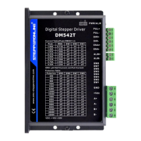
The Stepperonline Y Series Open-loop Stepper Driver is a digital stepper driver designed for smooth and efficient control of 2-phase and 4-phase stepper motors. These drivers are categorized by their driving power, including models such as DM420Y, DM542Y, DM556Y, and DM860Y. They are characterized by their simple design and ease of setup, making them suitable for applications requiring straightforward step and direction control for NEMA 8, 11, 14, 16, 17, 23, 24, and 34 stepper motors.

Function Description

The Y series drivers incorporate advanced stepper control technology to deliver optimal torque, reduced motor heating, and lower noise levels. Key functionalities include:

  • Anti-Resonance: This feature ensures optimal torque, extra smooth motion, and minimizes motor heating and noise.
  • Motor Auto-Identification and Parameter Auto-Configuration: The drivers can automatically identify connected motors and configure parameters for optimal torque across a wide range of motor types.
  • Control Method: They utilize step and direction (PUL/DIR) control, which is a common and effective method for stepper motor operation.
  • Multi-Stepping: This functionality enables smooth motor movement, reducing vibrations and improving overall performance.
  • Input Signals: The drivers feature TTL compatible and optically isolated inputs, enhancing noise immunity and signal integrity.
  • Soft-Start: When powered on, the drivers initiate with a soft-start sequence, preventing sudden "jumps" or erratic movements.
  • Automatic Idle-Current Reduction: This feature automatically reduces current when the motor is idle, minimizing heat generation and energy consumption.
  • Protections: Built-in protections safeguard against over-voltage and over-current conditions, ensuring the longevity and reliability of the driver and motor.

Important Technical Specifications

The Y series drivers offer various specifications depending on the model:

General Operating Environment:

  • Cooling: Natural cooling or forced cooling is recommended.
  • Environment: Avoid dust, oil fog, and corrosive gases.
  • Ambient Temperature: 0°C to 65°C (32°F to 149°F).
  • Humidity: 40%RH to 90%RH.
  • Operating Temperature: 0°C to 50°C (32°F to 122°F).
  • Vibration: 10-50Hz / 0.15mm.
  • Storage Temperature: -20°C to 65°C (-4°F to 149°F).
  • Weight:
    • DM420Y: 120g
    • DM542Y: 300g
    • DM556Y: 300g
    • DM860Y: 500g

Model-Specific Electrical Specifications:

DM420Y:

  • Output Peak Current: 0.3A (0.2 RMS) to 2.2A (1.6 RMS).
  • Supply Voltage: 18VDC (Min), 24VDC (Typical), 36VDC (Max).
  • Logic Signal Current: 7mA (Min), 10mA (Typical), 15mA (Max).
  • Pulse Input Frequency: 0kHz (Min) to 100kHz (Max).
  • Minimal Pulse Width: 5µs.
  • Minimal Direction Setup: 5µs.
  • Isolation Resistance: 500 MΩ.

DM542Y:

  • Output Peak Current: 1.0A (0.71 RMS) to 4.2A (3.0 RMS).
  • Supply Voltage: 20VDC (Min), 36VDC (Typical), 50VDC (Max).
  • Logic Signal Current: 7mA (Min), 10mA (Typical), 15mA (Max).
  • Pulse Input Frequency: 0kHz (Min) to 200kHz (Max).
  • Minimal Pulse Width: 2.5µs.
  • Minimal Direction Setup: 2.5µs.
  • Isolation Resistance: 500 MΩ.

DM556Y:

  • Output Peak Current: 1.7A (1.2 RMS) to 5.6A (4.0 RMS).
  • Supply Voltage: 20VDC (Min), 36VDC (Typical), 50VDC (Max).
  • Logic Signal Current: 7mA (Min), 10mA (Typical), 15mA (Max).
  • Pulse Input Frequency: 0kHz (Min) to 200kHz (Max).
  • Minimal Pulse Width: 2.5µs.
  • Minimal Direction Setup: 2.5µs.
  • Isolation Resistance: 500 MΩ.

DM860Y:

  • Output Peak Current: 2.4A (2.0 RMS) to 7.2A (6.0 RMS).
  • Supply Voltage: 18V(24)VAC/VDC (Min) to 80(110)VAC/VDC (Max).
  • Logic Signal Current: 7mA (Min), 10mA (Typical), 15mA (Max).
  • Pulse Input Frequency: 0kHz (Min) to 200kHz (Max).
  • Minimal Pulse Width: 2.5µs.
  • Minimal Direction Setup: 2.5µs.
  • Isolation Resistance: 500 MΩ.

Usage Features

Pin Assignment and Description (P1 Connector):

For DM420Y:

  • PU (Pulse Input): The falling edge is valid, causing one step. Built-in input resistor of 384 ohms. Requires low level 0~0.5V, high level consistent with common anode end, pulse width > 2.5 microseconds.
  • DR (Direction Input): Used to change motor direction. Built-in input resistor of 384 ohms. Requires low level 0~0.5V, high level consistent with common anode end, pulse width > 2.5 microseconds.
  • MF (Motor Free/Enable): When active (low level), the motor coil current is turned off, the driver stops working, and the motor is in a free state. Built-in input resistor of 384 ohms. Requires low level 0~0.5V, high level consistent with common anode end, pulse width > 2.5 microseconds.
  • +(5V) (Control Signal Power Supply): Can be driven by +3.3~24V. For voltages higher than +5V, a current limiting resistor must be added. For 3.3~5V, no current limiting resistor is needed. For 24V, a 2000 ohm resistor is used; for 12V, an 820 ohm resistor is used.

For DM542Y/DM556Y/DM860Y:

  • PU+ (Pulse Input Positive): Connected to the signal power supply. Can be driven by +5~+24V. For voltages higher than 24V, a current limiting resistor must be connected to PU-.
  • PU- (Pulse Input Negative): The falling edge is valid, causing one step. Requires low level 0~0.5V, high level 5~24V, pulse width > 2.5 microseconds.
  • DR+ (Direction Input Positive): Connected to the signal power supply. Can be driven by +5~+24V. For voltages higher than 24V, a current limiting resistor must be connected to DR-.
  • DR- (Direction Input Negative): Used to change motor direction. Requires low level 0~0.5V, high level 5~24V, pulse width > 2.5 microseconds.
  • MF+ (Motor Free/Enable Positive): Connected to the signal power supply. Can be driven by +5~+24V. For voltages higher than 24V, a current limiting resistor must be connected to MF-.
  • MF- (Motor Free/Enable Negative): When active (low level), the motor coil current is turned off, the driver stops working, and the motor is in a free state.

Wiring Configurations (P1 Interface):

The Y series open-loop drivers accept differential and single-ended inputs (open-collector and PNP output). Optically isolated logic inputs minimize electrical noise. Line drive control signals are recommended for increased noise immunity in interference environments.

  • Differential Wiring: For +5V, R1=0, R2=0. For +12V, R1=510Ω, R2=820Ω. For +24V, R1=1.2KΩ, R2=1.8KΩ.
  • Independent Common Anode Wiring: Similar resistor values apply for R1 and R2 based on voltage.
  • Common Anode Wiring: Similar resistor values apply for R1 and R2 based on voltage.
  • Independent Common Cathode Wiring: Similar resistor values apply for R1 and R2 based on voltage.

Motor Connections (P2 Connector):

  • 4-lead Motor: Connect A+, A-, B+, B-. NC pins are not used.
  • 6-lead Motor:
    • Half Coil (Higher Speed): Connect A+, A-, B+, B-. NC pins are not used.
    • Full Coil (Higher Torque): Connect A+, A-, B+, B-. NC pins are not used.
  • 8-lead Motor:
    • Series Connections: Connect A+, A-, B+, B-.
    • Parallel Connections: Connect A+, A-, B+, B-.
    • Half Coil: Connect A+, A-, B+, B-. NC pins are not used.

Troubleshooting (Frequently Asked Questions):

  • Motor not rotating: Check for power, fault conditions, or if the driver is disabled.
  • Motor rotates in wrong direction: Direction signal level might be reversed.
  • Erratic motor motion: Control signal might be too weak or interfered, wrong motor connection, or something wrong with the motor coil.
  • Motor stalls during acceleration: Current setting might be too small, motor undersized for the application, or acceleration is set too high.
  • Excessive motor and driver heating: Power supply voltage might be too low, inadequate heat sinking/cooling, or motor current setting is too high.

Maintenance Features

Heat Dissipation:

  • For all models (DM420Y, DM542Y, DM556Y, DM860Y), side mounting is recommended for better heat dissipation. This helps maintain optimal operating temperatures and prolongs the lifespan of the driver.

Warranty:

  • STEPPERONLINE® provides a 12-month warranty from shipment against defects in materials and workmanship.
  • During the warranty period, STEPPERONLINE will repair or replace defective products at its option.
  • To obtain warranty service, a Returned Material Authorization (RMA) number must be acquired before returning the product.

Exclusions from Warranty:

The warranty does not cover products damaged due to:

  • Improper or inadequate handling by the customer.
  • Improper or inadequate customer wiring.
  • Unauthorized modification or misuse.
  • Operation beyond the electrical specifications of the product.
  • Operation beyond the environmental specifications for the product.

For more detailed descriptions and specifications, customers are advised to refer to the official website: www.omc-stepperonline.com.

StepperOnline Y Series Specifications

General IconGeneral
BrandStepperOnline
ModelY Series
CategoryControl Unit
LanguageEnglish

Related product manuals