
J
Jeffrey AllenAug 19, 2025
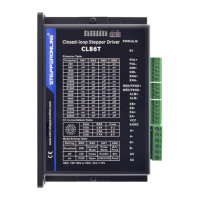
Why is my StepperOnline CL86T motor not rotating?
- AAmy YoungAug 19, 2025
If your StepperOnline Control Unit motor isn't rotating, ensure the power supply is correctly connected. Also, verify that the microstep resolution is appropriately set. Check for any existing fault conditions by inspecting the wiring and restarting the power. If the drive is disabled, restore the drive to its factory settings, and keep ENA+ and ENA- input signals unconnected.